MT526V03-01T-14977
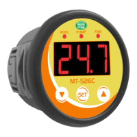
MT-526C
TEMPERATURE CONTROLLER
FOR HEAT PUMPS
V.03
1- DESCRIPTION
The becomes automatic the heat pump operation, enabling temperature control adjustments in
thermal reservoirs and pools for greater user comfort.
This instrument provides greater security to the equipment due to its digital inputs, which allow disarming the
system through high / low pressure controls and flow or temperature (depending on the adopted operation
mode). The heat pump operation can be configured to drive the full predetermined time after SCAN.
2 - APPLICATION
Heat pumps.
3 - TECHNICAL SPECIFICATIONS
- Direct power supply with internal transformer: 127 or 220Vac (50/60Hz)
- Control temperature: -50 to 105°C (resolution 0.1°C)
-58 to 221°F (resolution 1°F)
- Operating temperature: 0 to 50 °C
- Operating humidity: 10 to 90% RH (without condensation)
- Inputs:
Three temperature sensors:- S1: temperature in the heat pump's input
- S2: temperature in the evaporator
- S3: temperature in the heat pump's outlet *
* You must configure the operating mode of this input for it to operate as a temperature sensor.
See configuration table. This sensor is sold separately!
Three digital inputs: - LOW: low pressure switch
- HI: high pressure switch
- FLOW: flow switch**
** This input operates normally as a digital input for the flow switch. You must configure the operating mode of
this input for it to operate as a temperature sensor. See configuration table. This sensor is sold separately!
- Outputs:
Three relay outputs: - POOL: compressor actuation
- PUMP: Circulation pump
- FAN: Fan actuation
-Contact type: Normally open
-Maximum current: 5 A per output (resistive load)
- Dimensions: Diameter 60 mm, depth 40 mm
MT-526C
4.1 - To enter the function menu
- Simultaneously press buttons and for two seconds until [Fun] shows on the display.
When releasing the buttons, the message [F01] will be shown.
Press again (short press).
- Use buttons and to enter the access code (123) and when done, press .
- Use buttons and to access the desired function.
- After selecting the function, press (short press) to display the set value.
- Use buttons and to change the value, and when done, press to record the configured value and
return to the function menu.
- To exit the menu and return to normal operation, press (long press) until [---] appears.
4.2 - Parameters table
4.3 - Description of parameters
[F01]- Access code
When entering the access code (123), the controller allows the user to change the values of the other
parameters.
[F02]- Control differential (hysteresis)
Determines the temperature when the compressor turns on and off. If temperature S1 is below the "Control
temperature" minus "Control differential", the compressor is turned on. When the temperature is above the
"Control temperature" the compressor is turned off.
[F03]- Minimum setpoint allowed to the end user
Prevents the user to configure the "Temperature Control" with values too low.
[F04] - Maximum setpoint allowed to the end user
Prevents the user to configure the "temperature control" with values too high.
[F05]- Delay time for starting compressor (delay)
Whenever it is necessary to turn on the compressor, MT-526C will first turn on the fan. The controller waits
this amount of time set in this function before turning on the compressor.
[F06]- Temperature for starting defrost (***)
When temperature S2 is below the value set in this function, the controller starts the defrost cycle .
[F07]- Differential for completing defrost (***)
When the temperature S2 is above "Temperature for starting defrost" plus "Differential for completing defrost",
the controller finalizes the defrost cycle.
[F08]- Link the defrosting process to alarms
Allows to link defrosting process to the other alarms.
[,0,]- No
The defrosting process does not generate alarms.
[,1,]- Yes
The defrosting process generates an alarm and the controller will indicate the message [dEF]. For this
configuration, the MT-526C enable automatic resets depending on the value set in "Automatic reset
mode". The reset attempts to defrosting process will be added to the reset attempts of other alarms. The reset
process will occur after the "Delay time for reset" and only if the defrosting process has been finalized.
[F09]- Operating mode of input 3
Allows you to configure the operating mode of input 3.
[,0,]- Digital input (flow switch)
When configured as a digital input, it will have the function of monitoring the flow switch. In this way you can
see if the pump is on and if there is circulation between the heat pump and reservoir (SPA or pool).
[,1,]- Input of the temperature sensor 3
When configured as input to the sensor 3, MT-526C starts to monitor the heat flow between the heat pump
and the reservoir using the temperature difference between sensors 1 and 3.
[F10]- Delay time for the first scan
When the instrument is turned on, the first temperature scan will be performed after the time set in this
parameter.
[F11]- Scanning time
This parameter lets you adjust the operating time of the circulation pump and reservoir temperature scan.
During this process, the circulation of water between the heat pump and the reservoir determines the need to
turn on the compressor or not.
[F12]- Time between scans
This parameter lets you adjust the time between two temperature scans.
[F13]- Time to validate the flow switch
The lack of flow can be detected through the FLOW digital input (if F09 = 0) or using the third temperature
sensor S3 (if F09 = 1). For any of these detection forms of flow fault, validation occurs only after counting of the
programmed time set in this parameter.
The start of this time counting occurs every attempt to drive the pump (PUMP output) if F09 = 0. If F09 = 1, the
counting starts after start of the compressor (output POOL).
If the end of validation time a lack of flow is detected, the alarm [FLo] is activated. This validation time refers
only to the flow switch, the validation of the digital inputs linked with pressure switches occur instantly. This
feature prevents false triggering of lack of flow alarms. For any alarm ([PLo], [PHi] or [Flo]) all outputs
will be turned off.
[F14]- Linking flow switch to alerts
Enables linking the flow switch to other alerts.
[,0,] - No
The flow switch does not generate alert.
[,1,] - Yes
The flow switch generates an alert and the controller will indicate the message [Flo]. For this setting, the,
MT-526C will enable automatic resets depending on the value set to "automatic reset mode." Reset
attempts to the flow switch will be added to the reset attempts of other alerts. The reset for the flow switch will
occur after the "Delay Time to reset".
[F15]- Automatic reset mode
Allows you to configure the maximum number of automatic resets. If is detects any alarm ([Flo], [Plo],
[Phi]or[dEF]) the controller will attempt to reset after the time set in "Delay time for automatic resets". To
defrost alarms, beyond this delay time, the reset will occur only after the end of the defrosting process.
DescriptionFun
Min
Max
Unid
-
20.0
105.0
105.0
999
30.0
20.0
1
1
999
999
999
999
1
10
999
30.0
30.0
9
20
20
20
-
°C
°C
°C
Sec
°C
°C
-
-
Min
Min
Min
Sec
-
-
Min
°C
°C
-
°C
°C
°C
CELSIUS
-
1
-58
-58
0
5
1
0
0
0
0
0
0
0
0
1
1
1
0
-36
-36
-36
-
36
221
221
999
50
36
1
1
999
999
999
999
1
10
999
54
54
9
36
36
36
FAHRENHEIT
Min
Max
Unid
Standard
Standard
-
0.1
-50.0
-50.0
0
-15.0
0.1
0
0
0
0
0
0
0
0
1
0.1
0.1
0
-20
-20
-20
-
3
58
104
30
17
24
0
0
20
3
60
120
1
0
60
4
18
0
0
0
0
-
1.5
14.0
40.0
30
-8.0
13.0
0
0
20
3
60
120
1
0
60
2.0
10.0
0
0.0
0.0
0.0
[F01]
[F02]
[F03]
[F04]
[F05]
[F06]
[F07]
[F08]
[F09]
[F10]
[F11]
[F12]
[F13]
[F14]
[F15]
[F16]
[F17]
[F18]
[F19]
[F20]
[F21]
[f22]
Access code (123)
Control differential (hysteresis)
Minimum setpoint allowed to the end user
Maximum setpoint allowed to the end user
Delay time for starting compressor (delay)
Temperature for starting defrost (***)
Differential for completing defrost (***)
Link the defrosting process to alarms
Operating mode of input 3
Delay time for the first scan
Scanning time
Time between scans
Flow switch validation time
Linking flow switch to alerts
Automatic reset mode
Delay time for resets
Minimum temp. differential (S1-S3) (****)
Maximum temp. differential (S1-S3) (****)
Intensity of the digital filter
Offset indication of sensor 1 (offset 1)
Offset indication of sensor 2 (offset 2)
Offset indication of sensor 3 (offset 3) (*****)
-
°F
°F
°F
Sec
°F
°F
-
-
Min
Min
Min
Sec
-
-
Min
°F
°F
-
°F
°F
°F