F20 - Maximum time for fan return after draining (fan-delay)
For security, if the evaporator temperature does not reach the adjusted value in F19 or the S2 sensor is
detached, the fan-delay will happen after passed the adjusted time in this function.
F21 - Fan on with compressor off (in refrigeration)
During refrigeration, the fan can be depend of the compressor status.
”0” = The fan keeps turned on while compressor is turned on (this alternative, in some cases, possibilities a
great economy of electrical energy).
”1” = The fan keeps turned on during all refrigeration cycle.
F22 - Fan stop for high temperature in evaporator
This function cycles the evaporator fan until that ambient temperature approaches of the temperature
desired in the refrigerating installation project. This preventing high temperature and suction pressures
that can damage the compressor. If the temperature in evaporator pass the adjusted value, the fan is
turned off, turning on again with a configurable hysteresis in F23.
F23 - Differential for fan-delay (after stopping for high temperature in evaporator)
It allows to determine the difference of temperature to fan-delay had to a stop for temperature above
desired in evaporator.
F24 - Low temperature alarm (S1)
If the ambient temperature (sensor S1) decreases above this point during refrigeration, this will be
signalized through the message on display and the output (NO) of alarm will be turned on.
F25 - Alarm differential of low ambient temperature
It is the difference of temperature to turn off the alarm output for low ambient temperature.
F26 - High temperature alarm (S1)
If the ambient temperature (sensor) reaches this point during the refrigeration, this will be signalized
through the message on display and the output (NO) of alarm will be turn on.
F27 - Alarm differential of high temperature
It is the temperature to turn off the alarm output for high ambient temperature.
F28 - Inhibition time of alarm when the instrument is powered on
During this time the alarm is kept turned off waiting that the system starts to working.
F29 - Inhibition time of alarm after draining
This function serves to inhibit the alarm during a period after draining, because it is normal an elevation of
the temperature proceeding of the defrost.
F30 - Delay when the isnstrument is powered on
When the instrument is turned on, it can keep a time with its control disabled, delaying the process initial.
During this time it functions only as temperature indicator. It serves to prevent demand peaks of electrical
energy, in case of lack or return of the same, when a lot of equipments are connected in the same line. For
this, adjust different times for each equipment. This delay can be of compressor or defrost (when exists
defrost on start).
F31 - Minimum time of compressor turned on
It is the time that the compressor will keep turned on, it means, the time period between the last started and
the next stopped.
F32 - Minimum time of compressor turned off
It is the minimum time that the compressor will keep turned off, it means, the time period between the last
stopped and the next started. It serves to alliviate the pressure and to increase the useful life of the
compressor.
F33 - Compressor status with detached ambient sensor (S1)
If the ambient sensor (S1) is detached or out specified range, the compressor assumes the configured
status in this function.
Exemple: For counters that storage fruits it is better that the compressor keeps turned off, but in counters
that storage meats it is better that the compressor keeps turned on.
4.3.1 - Unit selection (ºC/ºF)
To determine the unit that the instrument will work, access the function “F01” with the access cod 231 and
confirm with the key . Press the key . will appear. Press than use or to choose
between or and confirm with . After select the unit will appear and the instrument
returns to the function “F01”. Every time that the unit is changed, the parameters must be configurated again,
because they assume the standard values (item 4.2).
5. OPERATION
5.1 - Parameters visualization
a) Press at the same time the keys and for 2 seconds until appear , releasing them after that.
Soon, appears .
b) Use the keys and to access the desired function.
c) After select the function, press (short touch) to visualize the configured value.
d) Press again (short touch) to return the functions menu.
e) To reset the menu and return to normal operation (temperature indication), press until appear .
SET
SET
SET
SET
SET
SET
5.2 - Parameters alteration
a) Access the function F01 pressing at the same time and for 2 seconds until appear ,
releasing then after that. Soon will appear , and then press (short touch).
b) Use and to enter the access code (123), and then press .
c) Select the desired function and visualize the configured value, like explained the itens“5.1-b” and
“5.1-c”.
d) Use and to change the value and then press to record the configured value and return
to the functions menu.
e) To reset the menu and return to normal operation (temperature indication), press until appear
.
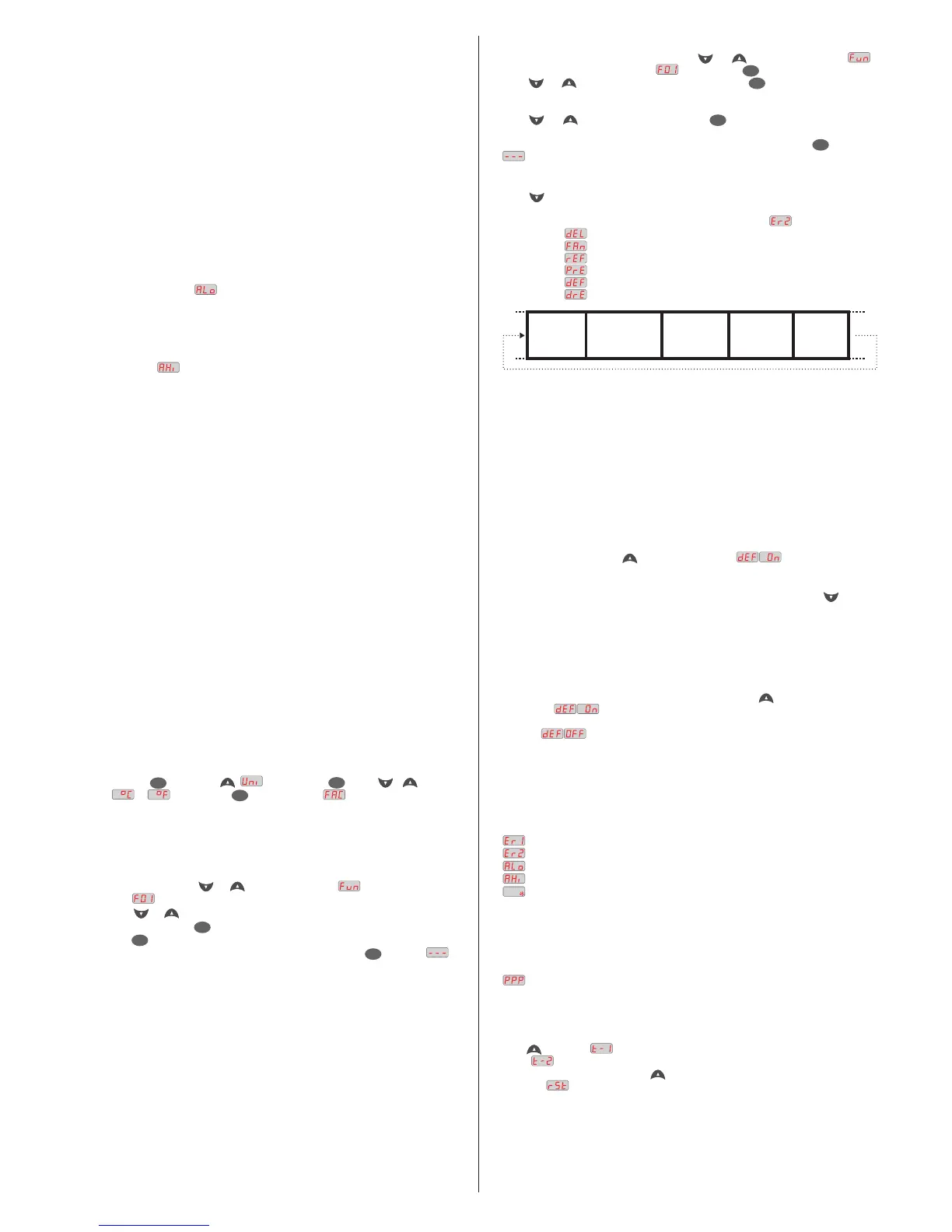
5.3 - Process stage, elapsed time and evaporator temperature (S2)
Press .The stage of the process will appear, the elapsed time (in minutes) and evaporator
temperature (S2).
In case of detached sensor or temperature out specified range will appear .
Process stages: Initial delay (delay to start the control)
Fan-delay (delay to fan return)
Refrigeration
Pre-defrost (only if F07 = 1)
Defrost
Draining
SET
SET
SET
SET
5.4 - Initial defrost condition
The function “F07” determines if the start of the defrost will be for time or temperature.
F07 = 0 The start of defrost will happen after elapsed the configured time in F08.
F07 = 1 When the temperature in the evaporator reaches the configured value in F10, the
count of pre-defrost period will start (F11). After elapsed this time, if the temperature keeps low the
defrost will start. If the temperature increases, the controller returns to refrigeration stage.
5.5 - How to determine the end defrost for temperature
a) Adjust the follow functions with maximum values:
- Interval between defrosts (F08 = 999 min)
- Evaporator temperature for end defrost (F13 = 75 ºC)
- Defrost maximum duration (F14 = 90 min)
b) Wait until an ice layer to be created on the evaporator.
c) Do a manual defrost, pressing or 4 seconds, until appear .
d) Observe the melting process.
FAN-DELAY
REFRIGERATION
DEFROST
DRAINING
PRE-DEFROST
e) Wait until melt all defrost on evaporator to consider the defrost finalized.
f) Check the temperature in evaporator read by the sensor S2 at this moment, pressing and copy
this value to the function F13 - Evaporator temperature (S2) for end defrost.
g) As security, adjust again the function F14 - Maximum duration of defrost, that depends of the defrost
type. Exemple: Electrical defrost (resistance) = 45 minutes as maximum
Defrost for hot gas = 20 minutes as maximum
h) Now adjust the function F08 - Interval between defrosts as desired value.
5.6 - Manual defrost
To do a manual defrost, regardless of the programming, keep pressed for 4 seconds, until appears
the indication .
If the instrument is in defrost and you want to finish it, follow the above instructions, until appears the
indication .
5.7 - Indicators and Alarms
The leds indicate the control outputs status:
REFR: Compressor or solenoid of liquid gas
FANS: Evaporator fans
DEFR: Defrost (resistances or hot gas)
ALRM: Alarm output
Detached ambient sensor or temperature (S1) out the range
Detached evaporator sensor or temperature (S2) out the range
Low ambient temperature alarm
High ambient temperature alarm
Always that the defrost is finished by time and not for temperature a point located on right inferior
side of display will be blinking until the next defrost, indicating that:
- The interval between defrost is too long.
- There are burned resistances
- The hot gas is not circulating
- There is an inoperative fan
- The adjusted time for maximum duration of defrost is short.
Invalid configuration parameters.
- In this situation the outputs will be turned off.
- Check which parameter have invalid information and correct it to return to normal operation.
5.8 - Registers of minimum and maximum temperatures
Press . Will appear and minimum and maximum temperatures of black sensor ( ambient). After
appear and minimum and maximum temperatures of gray sensor (evaporator).
Note: To reset the registers, keep pressed during visualization of minimum and maximum temperatures
until appear .

 Loading...