EasyManua.ls Logo

Fulleon ASSERTA User Manual

Fulleon ASSERTA
2 pages
To Next Page IconTo Next Page
Page #1 background imageLoading...
Page #1 background image
WARNING : On some tones the output level can exceed 120dB(A) @ 1m.
: Consult the relevant or appropriate health and safety regulations for guidelines.
Tones Table overleaf.
: Do not remove cover, refer servicing to qualified personnel.
: High voltage present within this equipment.
NOTE : Polar dispersion information available in the technical manual. (Ref:M03-003)
25-5643 Iss A
Dimensions
Ensure that guide
ribs are aligned.
(Top & Bottom)
2. Fixing Details
Mounting bracket.
(Optional extra)
NOTE: Ensure that the IP
integrity is maintained during
gland fitting.
(Take care not to disturb the
electronics while drilling.
Remove PCB if required)
Specification
Current Consumption
Construction
Operating Temperature
Tones
Operation
Operating Voltage Range
Sound Output @ 1m
Industrial Sounder (115Vac/230Vac)
0-80mA@115Vac
42 see table overleaf
-25°C to +75°C
ABS /PC Plastic Case
115Vac/230Vac 50/60Hz
Continuous
See table overleaf
168mm
168mm
155mm
1. Installation
3. Connection Detail
Knockout or drill required cable gland holes, and fix required
Fix base to wall in 4 positions.
115Vac/230Vac 110dB(A)
4. Sounder Settings
1. Volume Control
3. Switch 2 (Stage1 tone selection)
4. Switch 3 (Stage 2 tone selection)
1 42 3 5 6
OPEN
1 2 43
OPEN
5. Sounder Assembly
1. Plug the 5 way ribbon cable into the base header.
2. Ensure that the top indicator on the base is aligned with the
top indicator on the sounder, and push the sounder onto
3. Secure the sounder to the base using the bolts provided.
the base.
ASSERTA
Turn dial clockwise to increase volume.
(nominal 20dB Range)
2. Switch 1 (Time out setting)
OPEN
6532 41
See table overleaf.
See table overleaf.
(Stage 3 Tone is dependent on the setting of switch 2)
BIT 123X
111X
110X
100X
101X
Minutes
5
10
15
20
30010X
000X
001X
40
BIT 123X
011X
Minutes
25
Switch 1 bit 4 is to select voice (0)/ no voice (1). (Where fitted)
0 = Open
1 = Closed
1
2
3
4
cable glands.
90°
Ingress Protection IP66
117mm
148mm
Stage 2
Stage 1
Stage 3
COM
L
N
L
N
0-40mA@230Vac
Maximum Power 9W
42 see table overleaf
115Vac/230Vac 50/60Hz
115Vac/230Vac 120dB(A)
ABS /PC Plastic Case
-25°C to +75°C
IP66
0-65mA@230Vac
0-130mA@115Vac
See table overleaf
Continuous
15W
NOTE: A readily accessible
disconnect device must be
incorporated in the mains
supply wiring to this unit.
Fuse 80mA Anti surge, 20mm 80mA Anti surge, 20mm
Hole positions for additional cable entries.
Knock outs for cable entries.
(Top & Bottom)
Set switch to correct
requirement for installation.
(115Vac or 230Vac)

Other manuals for Fulleon ASSERTA

Question and Answer IconNeed help?

Do you have a question about the Fulleon ASSERTA and is the answer not in the manual?

Fulleon ASSERTA Specifications

General IconGeneral
BrandFulleon
ModelASSERTA
CategoryMarine Equipment
LanguageEnglish

Summary

Sounder Specification

Operation and Voltage

Specifies continuous operation and the operating voltage range for the sounder.

Sound Output and Current

Details sound pressure level at 1m and current consumption at different voltages.

Maximum Power and Tones

Indicates maximum power consumption and the number of available tones.

Environmental and Protection Ratings

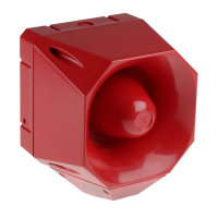
Covers operating temperature, construction materials, and ingress protection (IP66).

Fuse Details

Specifies the type and rating of the anti-surge fuse for protection.

Dimensions

Installation and Fixing

Cable Gland Installation

Procedure for drilling and fitting cable gland holes while maintaining IP integrity.

Mounting and Fixing

Instructions for securely fixing the sounder base to a wall in four positions.

Connection and Wiring

Electrical Connections

Details on connecting the sounder, including ribbon cables and mains supply wiring.

Mains Disconnect Requirement

Mandatory inclusion of a readily accessible disconnect device in the mains supply.

Sounder Settings and Assembly

Volume and Tone Configuration

Adjusting volume and selecting tones using rotary controls and DIP switches.

DIP Switch Functions

Configuration of time-out settings, stage 1/2 tone selection, and voice/no voice.

Physical Assembly

Steps for connecting the ribbon cable and securing the sounder to its base.

Industrial Sounder Tones Table

Tone Codes and Patterns

Catalog of sounder tone codes, patterns, frequencies, and descriptions.

Sound Output Levels

Details sound pressure levels at 1m for 115Vac/230Vac Low and High Power.

Stage 3 Tone Indicators

Indicates the assigned Stage 3 tone for each sounder code.

Tone Applications and Use

Specifies the intended use and region for each sounder tone pattern.