© Fulton Group N.A., Inc. 2021
3-22
OPERATION ModSyncSE-User-Manual-211020 SECTION 3
! WARNING
This manual is provided as a
guide to the correct operation and
maintenance of your equipment,
and should be read in its entirety and
be made permanently available to
the sta responsible for equipment
operation. It should not, however
be considered as a complete code
of practice, nor should it replace
existing codes or standards which
may be applicable. Fulton reserves
the right to change any part of
this installation, operation and
maintenance manual without notice.
Do not install, operate, service,
or repair any component of this
equipment unless you are qualied
and fully understand all requirements
and procedures.
All information in this manual is for
reference and guidance purposes,
and does not substitute for required
professional training, conduct,
and strict adherence to applicable
jurisdictional /professional codes or
regulations
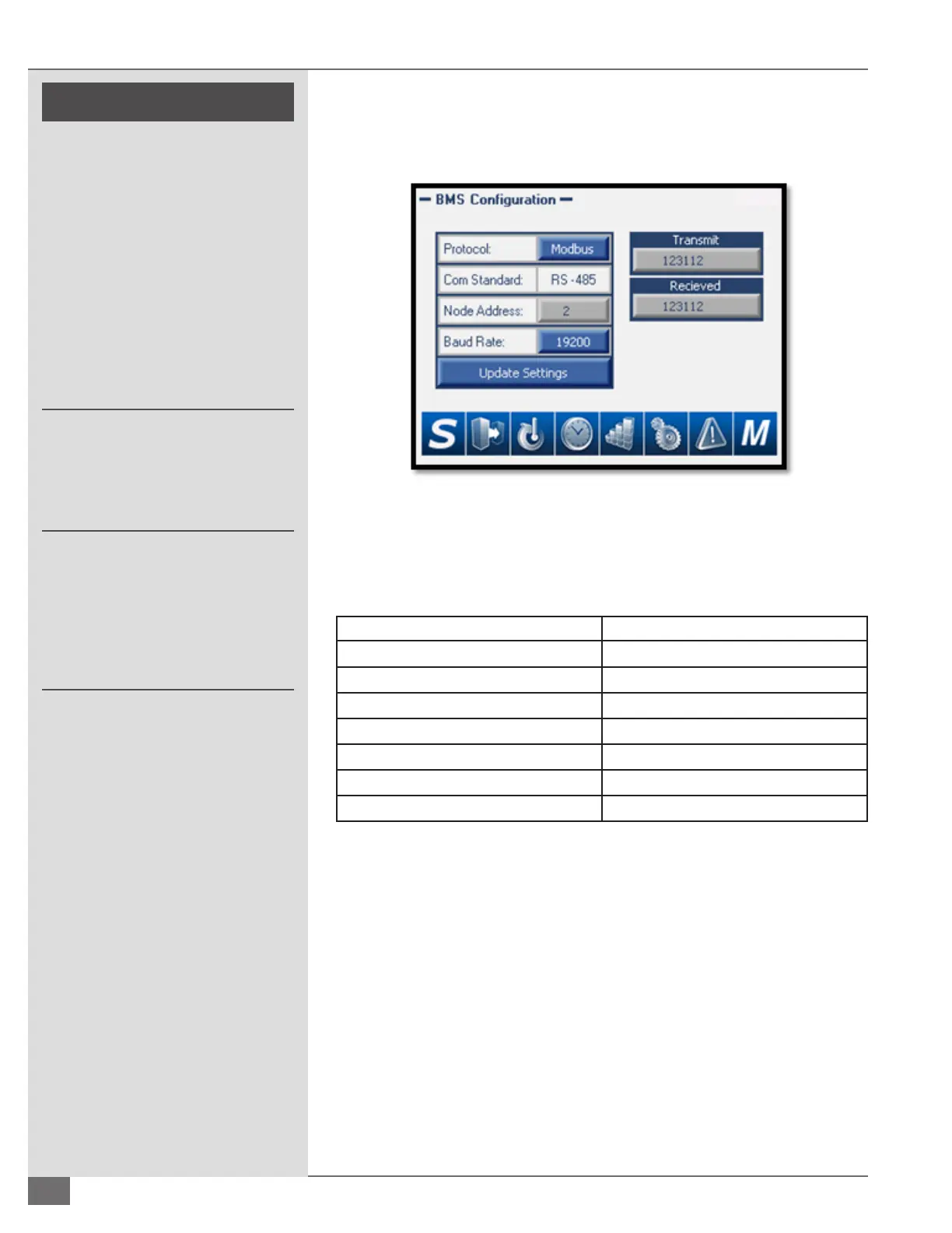
BMS Configuration (Port 2)
Used to congure the communication settings to the Building Management
System.
Protocol: The ModSync® oers three options for protocol (Modbus,
BACnet, and LonWorks). The ModSync® comes standard with Modbus
communication. If BACnet or LonWorks communication is required, a
separate protocol converter is required.
Parameter Setting
Protocol Modbus RS485 RTU
Baud Rate 9600, 19200, 38400, 57600
Start Bits 8
Parity None
Stop Bits 1
Timeout 5 seconds
Nodes Up to 20
NOTE: The settings above are used for conguring Modbus communication only.
If using BACnet, LonWorks, or another communication protocol the ModSync®
will have been provided with a communication gateway. For the ModSync® to
properly communicate to the Gateway please select Node Address 2 and a baud
rate of 19200. Once the settings have been changed, a message will appear
advising that the settings need to be updated. Press the Update Settings button
and the message will change to communication settings updated. The ModSync®
is now properly congured with settings selected. Transmit and Receive values to
the right are available to show communication status.
FIGURE 19– BMS CONFIGURATION SCREEN
 Loading...