Questions? Please Contact Your Local Manufacturer’s Representative
3-25
SECTION 3 ModSyncSE-User-Manual-211020 OPERATION
! WARNING
This manual is provided as a
guide to the correct operation and
maintenance of your equipment,
and should be read in its entirety and
be made permanently available to
the sta responsible for equipment
operation. It should not, however
be considered as a complete code
of practice, nor should it replace
existing codes or standards which
may be applicable. Fulton reserves
the right to change any part of
this installation, operation and
maintenance manual without notice.
Do not install, operate, service,
or repair any component of this
equipment unless you are qualied
and fully understand all requirements
and procedures.
All information in this manual is for
reference and guidance purposes,
and does not substitute for required
professional training, conduct,
and strict adherence to applicable
jurisdictional /professional codes or
regulations
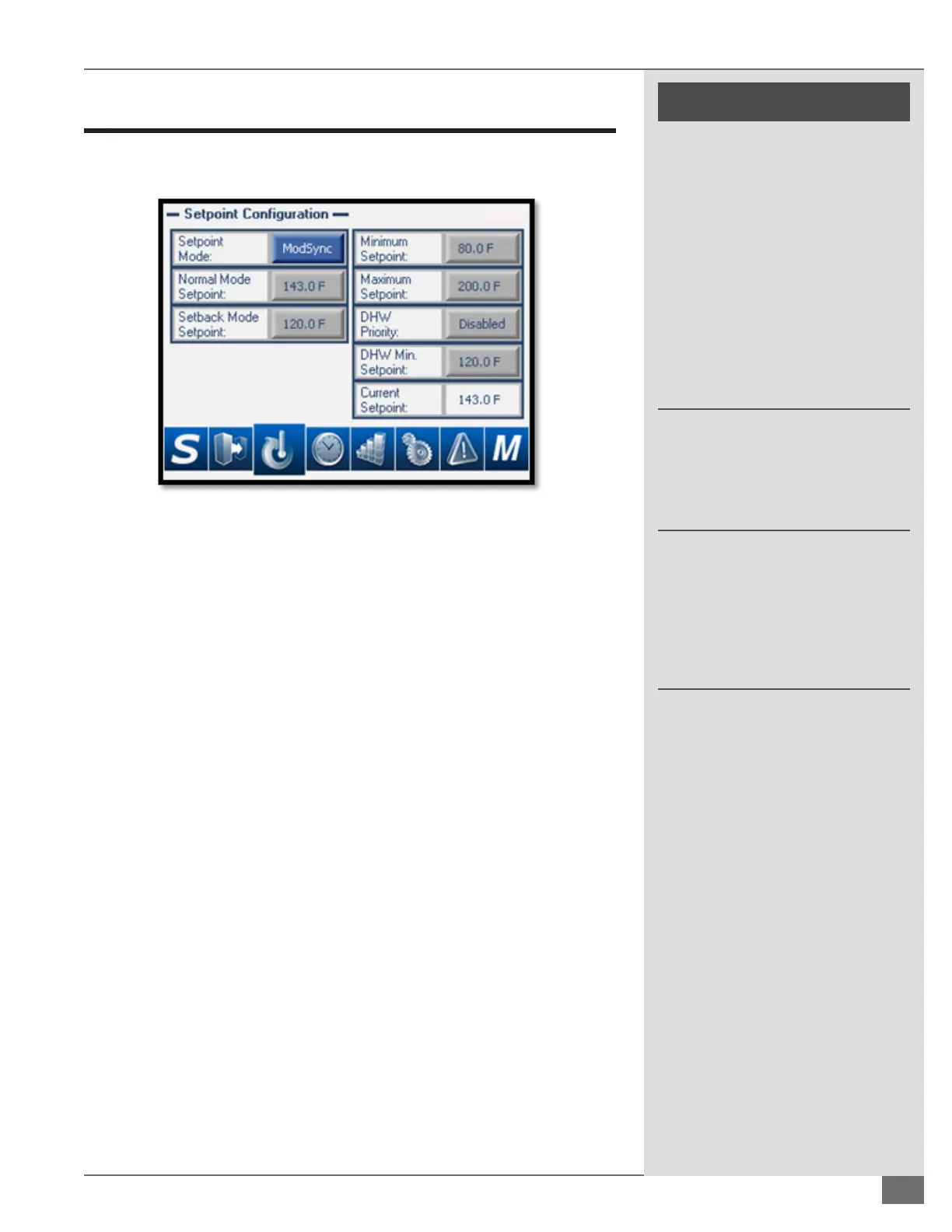
Setpoint Configuration without Outdoor Reset
The Setpoint Conguration screen displayed is based on the option selected.
Below is the Setpoint Conguration screen without outdoor reset.
FIGURE 23 – SETPOINT CONFIGURATION WITHOUT OUTDOOR RESET
Setpoint Mode: Determines where the ModSync® determines where the
loop setpoint is generated from.
» ModSync®: The setpoint will be the user selected Normal
Mode Setpoint or Setback Mode Setpoint based on the setback
schedule.
» Remote SP: The setpoint will be determined by the 4-20mA
signal input scaled from the system and scaling screen.
» BMS: The setpoint will be written by the Building Management
System through the communication protocol.
Minimum Setpoint: User selected value that will limit the minimum that
the ModSync® will allow the setpoint to get to regardless of the setpoint
mode. For example if the setpoint mode is in BMS and the BMS is writing a
100°F setpoint to the ModSync® but the Minimum Setpoint is set for 120°F
then the ModSync® setpoint will be 120°F.
Maximum Setpoint: User selected value that will limit the maximum that
the ModSync® will allow the setpoint to get to regardless of the setpoint
mode. For example if the setpoint mode is in BMS and the BMS is writing a
180°F setpoint to the ModSync® but the Maximum Setpoint is set for 160°F
then the ModSync® setpoint will be 160°F.
DHW Priority: In the event that the Heating Loop is also providing heat
for Domestic Hot Water production the ModSync® comes equipped with
DHW Priority logic. When Enabled, if the contact between M1 and 1B
(Please see your ModSync® electrical drawing) is made the ModSync® will
enter DHW mode.
DHW Min Setpoint: If the ModSync® is in DHW mode and the current
setpoint is less than the DHW Min Setpoint then the ModSync® will raise
the setpoint up to the DHW Min Setpoint until the ModSync® is no longer
in DHW mode.
 Loading...