Panel Max AssemblyWall Mounting Boards
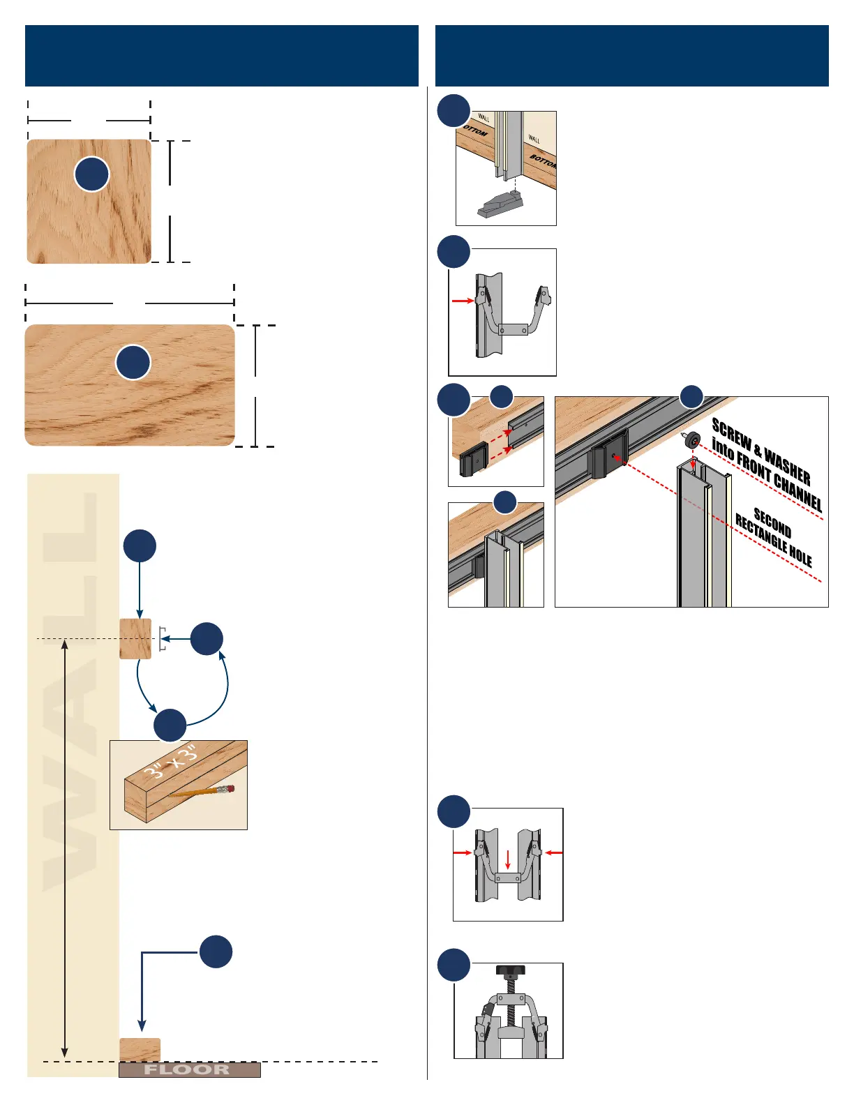
1. Attach the Stabilizing Foot in the
bottom of the Side Pressure Bar
that is going against the wall. The
tapered end Must Be facing away
from the wall as shown in g 1.
2
3
A B
C
2. Insert the Bottom Pressure As-
sembly into the pressure bar that
is going to be against the wall as
shown in g 2. The Bottom Pressure
Assembly should be set at the 4th
hole down for assembly process.
1
3. Insert the Slide Attachment (2) into the Slide Rail
(1) (g. 3A). Insert a Short Screw (12) through a Nylon
Washer (11) (g. 3B). Slide the screw & washer down
through the front channel and insert the screw &
washer into the second rectangular hole from the top
(g. 3B). Align the screw with the Slide Attachment (2)
and insert the screw into the pre-drilled hole (g. 3B).
Secure with a philips head screw driver (g. 3C).
1. Cut a piece of lumber -
that is 3” x 3” and at least
as long as the Panel Max
Slide Rail.
3. Mount the 3” x 3”
piece to your wall 41” on
center from the oor.
4”
3”
3”
BOTTOM
3”
TOP
2
1
41” from oor to center
3
4
6
5
2. Cut a piece
of lumber -
that is 4” x 3”
and at least
as long as the
Panel Max
Slide Rail.
4. Draw a line the en-
tire length of the 3” x
3” that is exactly 41” on
center from the oor
5. Attach the Slide Rail
to 3” x 3” piece of stock
(top piece) using 3 wood
screws and use the line
made in step #4 as a
guide
6. Mount the 4” x 3”
piece to the base or
close to the base of your
wall, making sure it is
parallel to the oor.
4
4. Place the second Side Pressure
Bar on to the Stabilizing Foot. At-
tach the lower pressure bar assem-
bly to the second side pressure bar
by sliding the spring loaded clip in
from the top of the second pres-
sure bar as shown in g 4.
5. Install the Top Pressure Assem-
bly into the two Side Pressure Bars
from the top side as shown in g 5.
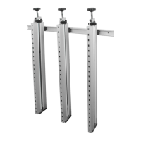
Repeat Panel Max Assembly steps
for each vertical press clamp.
5
 Loading...