Mounting Bolt Torque 28-30 ft./lbs. 28-30 ft./lbs.
Installation Instructions
Mounting Hardware Requirements
Refer to Table 2 below for bolt quantity, sizes, and required torque. Mounting system will dictate bolt
length.
ALWAYS torque mounting bolts to the values specified for your winch in Table 2.
ALWAYS use grade 5 (class 8.8 metric) hardware.
NEVER weld mounting bolts.
ALWAYS choose the proper bolt length for your application.
ALWAYS confirm required bolt length to ensure proper thread engagement. A minimum of two whole
threads should protrude from the nut.
1.2 Select Mount Location
ALWAYS choose a mounting location that is sufficiently strong to withstand the maximum
pulling capacity of your winch.
1.2.1 Winch Mounting
Considerations
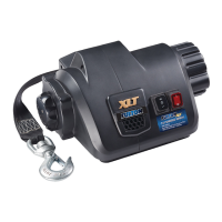
Your mounting surface must be equal to or
greater than the mounting surface of the
winch frame. See Figure 3. Three sets of
3/8”, Grade 5, hardware are required to
mount this winch.
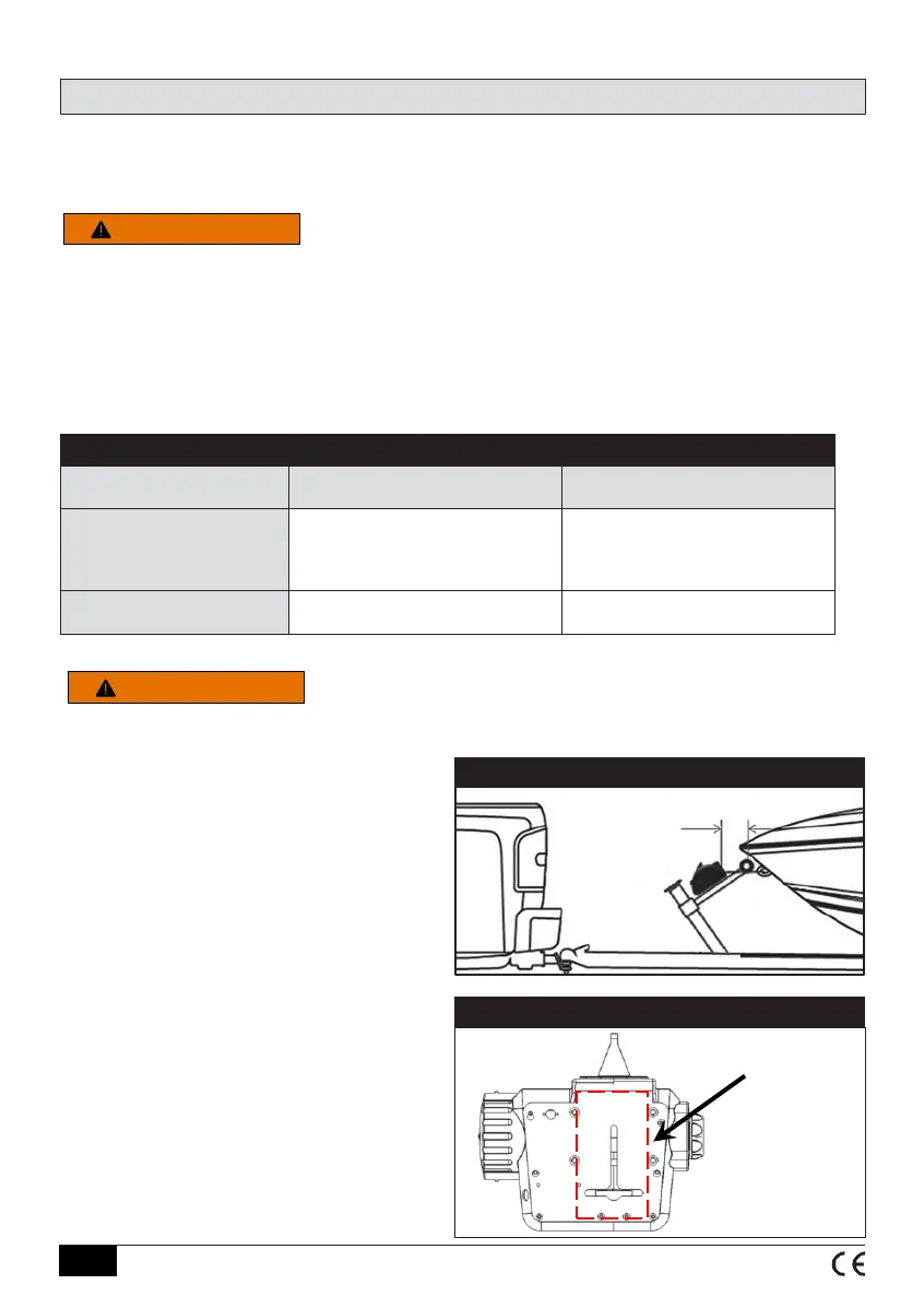
The winch should be positioned so that the
strap exits the winch horizontal to the bow
eye when the boat is fully loaded onto the
trailer.
The fairlead should be a minimum of 6” away
from the bow eye when the boat is fully loaded
onto the trailer. See Figure 2.
Figure 3 - MountingSurface
Minimum
Mounting
Area
4.5” x 6”
Figure 2 - MountLocation
Minimum distance
from the bow eye to
the winch, when the
boat is fully loaded
on to the trailer
6”
WARNING
©2021 Horizon Global Americas Inc. • F4088-00 REV D (7871) 08/2021
E6