Do you have a question about the Furness controls FCO432 and is the answer not in the manual?
Overview of the FCO432 differential pressure transmitter, its capabilities, and applications.
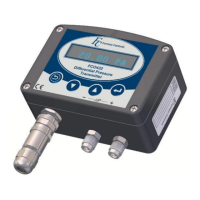
Describes the IP54 rated ABS enclosure and pneumatic connection types.
Recommends mounting position, notes vibration sensitivity, and mentions mounting holes.
Specifies pipe-work slope for self-draining and reference port connection.
Details the M12 connector type, pin functions for different configurations, and connection diagrams.
Describes the FCS541 400 Utility software for configuring and calibrating 400 series instruments.
Details USB-B and optional RS232 connections and the step-by-step installation procedure.
Explains setting custom values, reading/writing configurations, and using View Display and Test a Device tabs.
Describes how to save and load instrument settings using the software.
Explains saving transmitter settings to a text file.
Outlines the hierarchical structure of the instrument's settings menu.
Explains how to navigate the instrument's menu using the keypad and software.
Describes the purpose and use of the PIN security code for accessing the menu.
Details how to set or disable the PIN security code.
Explains the purpose of the filter and its considerations for response time.
Explains how to set the display to show engineering units, custom values, or square root.
Details the available pre-calibrated engineering units for display.
Describes setting up user-defined display units for CUST or ROOT display modes.
Sets the differential pressure corresponding to the minimum output level.
Sets the differential pressure corresponding to the maximum output level.
Alters the position of the display decimal point for CUST or ROOT modes.
Sets the display value for the minimum output level.
Sets the display value for the maximum output level.
Contains settings for configuring instrument relays, including function, set/reset levels, and delay.
Alters the operational function of the relay between HYST and BAND modes.
Sets the display reading at which the relay changes to the ON state.
Sets the display reading at which the relay changes to the OFF state.
Alters the delay time before the relay goes into its de-energised state.
Selects conditions for visual alarms on the FCO432 display.
Explains the rules for HYST and BAND relay operations and fail-safe conditions.
Alters the interval time after which the instrument automatically zeros itself.
Describes how the automatic zero function works, including freezing display/output.
Explains how to prevent manual zeroing using the zero button or serial commands.
Defines an additional purge time to vent residual pressure from the unit.
Sets the output to a pre-set value for test purposes.
Contains settings for serial communications, including Baud rate and Fbus ID.
To set the communications Baud rate for serial communications.
Sets the Fbus ID number for identifying the unit with Fbus communications.
Used to delay the instrument's response to an fbus communication command.
Puts the unit into its Flash Updating mode for program updates.
Allows defining linearity correction points to correct for non-linearity.
Sets the five linearity correction points and required adjustments.
Sets the five linearity correction errors present at the defined points.
Sets the output level (MIN/MAX) in the event of an instrument fault.
Displays the current instrument program firmware installed.
Displays the instruments factory defined Serial number.
Displays the instruments factory defined Unit ID number.
Details under-scale, over-scale, and fault output levels for different configurations.
Provides guidance on resolving issues with adjusting the decimal point.
Explains that '----' indicates pressure below minimum and suggests zeroing.
Explains that '++++' indicates pressure above current scaling.
Explains keypad behaviour for changing numeric values and resetting digits.
Advises contacting Furness Controls to restore a lost PIN number.
Calibration data stored in EEPROM may have become corrupted.
User data stored in EEPROM may have become corrupted.
Main signal ADC failed to get a conversion within its timeout period.
Temperature sensor bit reading is outside the 0-7000 range.
Auto-zero valve sensor detected a fault; check 24V supply.
Extended calibration data in EEPROM may have become corrupted.
Extended user data in EEPROM may have become corrupted.
Diagnostic signal ADC received invalid readings, likely faulty.
Diagnostic circuitry detected a problem with the 4-20mA output current.
Diagnostic circuitry detected a problem with pressure transducer output voltage.
A write error was detected when updating settings in EPROM data.
Guides on checking output levels and adjusting minimum/maximum output and gain via keypad.
Details how to adjust instrument gain using the keypad.
States that these adjustments should only be carried out by Furness Controls.
Provides formulas for calculating velocity from AP and AP from velocity.
Formulas for calculating volumetric flow rate from velocity and velocity from flow.
Formula for calculating mass flow rate using volumetric flow and density.
Provides formulas for calculating flow and AP related to laminar flow elements.
Details using the transmitter to measure differential pressure and scale the output.
Explains using the FCO432 with an LFE for flow measurement, including configuration.
Describes using the FCO432 with a Pitot Static Tube for flow measurement, including configuration.
Describes the optional M12 (4-pole) connection and its wiring.
Details the DIN connection type, pin functions, and wiring diagrams.
Explains the DIN connection with an external switch for zeroing the instrument.
Lists models, ranges, output options, keypad, and measurement functions.
Details accuracy, span adjustment, drift, temperature coefficients, output resolution.
Covers enclosure, dimensions, materials, and media compatibility.
Provides dimensional drawings and measurements for the basic instrument unit.
Shows dimensional drawings for the pipe mounting kit.
Provides dimensional drawings and measurements for the wall mounting kit.
| Brand | Furness controls |
|---|---|
| Model | FCO432 |
| Category | Transmitter |
| Language | English |