EasyManua.ls Logo

Furuno AIS Transponder FA-50 User Manual

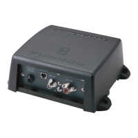
Furuno AIS Transponder FA-50
65 pages
To Next Page IconTo Next Page
Page #1 background imageLoading...
Page #1 background image
www.furuno.co.jp

Questions and Answers:

Furuno AIS Transponder FA-50 Specifications

General IconGeneral
BrandFuruno
ModelAIS Transponder FA-50
CategoryCar Navigation system
LanguageEnglish

Summary

SAFETY INSTRUCTIONS

Safety Instructions for the Operator

Provides critical safety guidelines for users operating the FA-50 transponder.

Safety Instructions for the Installer

Provides essential safety guidelines for individuals installing the FA-50 transponder.

FOREWORD

A Word to the Owner of the FA-50

Welcomes the owner and introduces the FA-50 AIS Transponder, emphasizing quality and reliability.

Features of the FA-50

Details the capabilities and functions of the FA-50 AIS Transponder, including data exchange and compliance.

Program Version Information

Lists program version, number, and release date for the FA-50 transponder.

SYSTEM CONFIGURATIONS

INSTALLATION

Equipment List (Standard Supply)

Lists all standard supply items included with the FA-50 transponder for initial setup.

Optional Supply Items

Lists optional equipment and accessories available for expanding the FA-50 system's functionality.

AIS Transponder FA-50 Mounting

Provides mounting considerations and procedures for the FA-50 transponder unit, ensuring stable placement.

VHF Antenna Location and Installation

Details guidelines for optimal placement and installation of the VHF antenna to minimize interference.

VHF Antenna Cabling Guidelines

Describes recommended practices for installing coaxial cables for the VHF antenna, ensuring signal integrity.

GPS Antenna Mounting and Cable Extension

Covers mounting the GPS antenna and extending its cable for optimal signal reception.

Connector Attachment for 8D-FB-CV Cable

Step-by-step instructions for attaching the N-P-8DFB connector to the 8D-FB-CV cable.

GPS/VHF Combined Antenna Installation

Details the mounting and installation procedure for the GPS/VHF combined antenna unit.

Distributor DB-1 Installation Procedure

Provides instructions for mounting and installing the DB-1 distributor unit within the system.

AC-DC Power Supply Mounting

Covers mounting considerations and procedures for the optional AC-DC power supply unit.

Wiring Diagram and Connections

Illustrates power, antenna, and data connections for the FA-50 system, ensuring correct setup.

AIS Viewer (FAISPC-MX) Connection Examples

Shows different connection configurations for the AIS viewer, illustrating direct and network setups.

COM PORT and Network Setup

Guides through configuring COM port and network settings for the FA-50, enabling communication.

COM PORT Setup Details

Explains data type and speed settings for the COM port configuration, ensuring compatibility.

Network Setup Configuration

Details IP address, subnet mask, and host name settings for network connectivity.

Ship Static Data Configuration

Covers setting up static ship information like MMSI and vessel type for AIS transmission.

Ship Static Data Entry

Details how to enter MMSI, ship name, call sign, and antenna positions accurately.

OPERATION

FA-50 Transponder Overview

Describes the FA-50's power status, LEDs, and basic operational indicators.

Sending Pre-defined Messages

Explains how to send pre-defined messages from the FA-50 to other vessels or stations.

Confirming Received Messages

Describes how to view and check received messages in the RX Log for communication history.

Own Vessel Data Display Screen

Shows how to access and interpret the display of the vessel's own data on the FA-50.

Cargo Type and Region List Details

Explains how to select cargo type and view region details for enhanced vessel information.

Group Assignment Window

Describes the group assignment window for receiving messages via VHF based on geographical area.

Alarm Status Indications and Meanings

Lists and explains various alarm status indications and their meanings for system monitoring.

Sensor Status Display Information

Provides information on the status of connected sensors, ensuring data availability.

MAINTENANCE, TROUBLESHOOTING

Routine Maintenance Checks

Outlines monthly checks to maintain good performance and working order of the equipment.

Replacing the Fuse

Step-by-step guide for replacing a blown fuse in the FA-50 to restore power.

Troubleshooting Common Problems

Provides a table of common symptoms, problems, and their remedies for quick issue resolution.

Built-in Diagnostics Tests

Explains how to use the diagnostic facility to check equipment operation and identify faults.

APPENDIX 1 MENU TREE

APPENDIX 2 VHF CHANNEL LISTS

VHF Channel Lists - International Mode

Lists VHF channel numbers and their corresponding frequencies for international mode operation.

APPENDIX 3 PARTS LIST, LOCATIONS

Transponder Parts Location

Shows the physical location of major internal components within the FA-50 transponder.

APPENDIX 4 DIGITAL INTERFACE

Serial Interface I/O Circuit Details

Illustrates the circuit diagram for the serial interface input/output, detailing connections.

DSC, DSE, and DTM Sentence Formats

Details the formats for DSC, DSE, and DTM NMEA sentences used for communication.

GBS, GGA, and GLL Sentence Formats

Describes the formats for GBS, GGA, and GLL NMEA sentences used for GPS data.

GNS, HDT, and OSD Sentence Formats

Details the formats for GNS, HDT, and OSD NMEA sentences for navigation data.

RMC, SSD, and VBW Sentence Formats

Explains the formats for RMC, SSD, and VBW NMEA sentences for recommended and static data.

VSD, VTG, and ABK Sentence Formats

Describes the formats for VSD, VTG, and ABK NMEA sentences for voyage and acknowledgement data.

ACA, ACS, and ALR Sentence Formats

Details the formats for ACA, ACS, and ALR NMEA sentences for channel management and alarms.

TXT, VDM, and VDO Sentence Formats

Explains the formats for TXT, VDM, and VDO NMEA sentences for text and data link messages.

SPECIFICATIONS

General Specifications

Covers general type, RX capacity, operating mode, and regulations of the FA-50.

Transmitter Specifications

Details the frequency range, output power, and emission characteristics of the transmitter.

AIS Receiver Specifications

Lists receiver frequency, sensitivity, and rejection characteristics for AIS signals.

DSC Receiver Specifications

Covers frequency, sensitivity, and error at high input level for the DSC receiver.

Interface Specifications

Describes COM I/O, Network, and function alarm interfaces of the FA-50.

Power Supply and Environmental Conditions

Details power requirements and operating environmental conditions for the FA-50.

Environmental Conditions and Coating Color

Covers bearing vibration and coating colors for antenna unit and transponder.

PACKING LIST

INSTALLATION MATERIALS LIST

OUTLINE DRAWING

Antenna Unit Outline Drawing

Shows the dimensions and details of the antenna unit for installation reference.

GPS/VHF Combined Antenna Outline Drawing

Presents dimensional drawings for the GPS/VHF combined antenna for installation planning.

Distributor DB-1 Outline Drawing

Displays the dimensional specifications for the DB-1 distributor for mounting purposes.

150MHz Whip Antenna Outline Drawing

Provides dimensional drawings for the 150MHz whip antenna for installation.

ANTENNA MOUNTING LOCATION AND PROCEDURE

INTERCONNECTION DIAGRAM