EasyManua.ls Logo

Furuno FM-4000 - User Manual

Furuno FM-4000
84 pages
Print Icon
To Next Page IconTo Next Page
Loading...
Page 1FM-4000
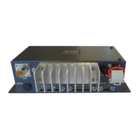
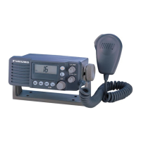
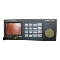
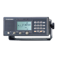
MARINE VHF RADIOTELEPHONE
With Class D DSC Modem and CH70 with receiver
FM-4000
Owner’s Manual
l
l
l
l
l
l
l
l
l
l
l
l
l
l
l
**
When attached to GPS Receiver
Commercial grade ITU class D DSC transceiver
Superior receiver performance (80 dB rejection)
30W LoudHailer complete with listen-back and four fog horns, bells, and
whistle
2.2-inch internal speaker produces clear, loud audio
2.58" x 1.28" dot matrix display
Alphanumeric keypad allows direct entry of channel numbers or selection of
most used functions
NAV mode displays latitude/longitude, position, time, SOG, COG*
Oversized rotary selector, volume and squelch knobs
Programmable scan, selectable priority scan, and dual watch
One-button access to CH16 and CH9
Treble and bass audio tone control
Two inputs for optional Remote MIC
Optional voice scrambler
Multi-station intercom
High and low voltage warnings

Table of Contents

Questions and Answers

  • R
    Rebecca BanksAug 15, 2025
    Why does my Furuno Telephone transceiver blow a fuse when connected to the power supply?
    • J
      Jon PerezAug 15, 2025
      The fuse might blow due to reversed power wires. Check the power cable for DC voltage and ensure the red wire connects to the positive (+) battery post, and the black wire connects to the negative (-) battery post. Also, check the fuse (6A 250V). If the fuse continues to blow after replacement, it is recommended to contact your dealer for advice.
  • E
    Erin OlsenAug 18, 2025
    What to do if "HI BATTERY" or "LO BATTERY" appears on my Furuno Telephone?
    • K
      Kim CookAug 18, 2025
      If you see a “HI BATTERY” or “LO BATTERY” message when you turn on your Furuno Telephone, it indicates that the power supply voltage is either too high or too low. Verify that the connected power supply voltage is not over 17 volts or lower than 10 volts.
  • D
    Dorothy MorrisAug 21, 2025
    What to do if my Furuno Telephone position is not displayed?
    • J
      Joshua MoraAug 22, 2025
      If your position is not displayed on your Furuno Telephone, check the accessory cable to ensure it's firmly fastened. Some GPS receivers use the battery ground line for NMEA connection. Also, verify the output signal format of the GPS receiver. This radio requires NMEA0183 format with GLL, RMB, or RMC sentence as an output signal. If the GPS receiver allows setting baud rate and parity, select “4800” and “NONE,” respectively.
  • S
    Sandra MooreAug 25, 2025
    What to do if the sound is not emitted from the internal or external speaker of my Furuno Telephone?
    • P
      Pamela OrrAug 25, 2025
      If no sound comes from the internal or external speaker of your Furuno Telephone, check if the accessory cable is firmly fastened. You can also short circuit the external speaker cable WHITE/ SHIELD.
  • M
    Michael GreeneAug 27, 2025
    How to fix popping or whining noise from the speaker of Furuno Telephone while engine runs?
    • M
      Michael DavisAug 27, 2025
      If you hear popping or whining noises from the Furuno Telephone speaker while the engine is running, it's likely due to engine noise. Try rerouting the DC power cables away from the engine. You can also add a noise suppressor on the power cable or switch to resistive spark plug wires and/or add an alternator whine filter.
  • D
    Daniel PearsonAug 30, 2025
    What to do if the sound is not emitted from the PA speaker of my Furuno Telephone?
    • A
      Alan RhodesAug 30, 2025
      If sound is not emitted from the PA speaker on your Furuno Telephone, make sure the accessory cable is firmly fastened. Short circuit the PA speaker cable RED/ SHIELD to test.
  • J
    Jessica WilliamsSep 2, 2025
    What to do if “PA ERROR” or “FOG ERROR” is shown on Furuno Telephone?
    • A
      Austin ReyesSep 2, 2025
      If “PA ERROR” or “FOG ERROR” appears when the PA/FOG mode is activated on your Furuno Telephone, verify that the accessory cable is firmly fastened. Short circuit the PA speaker cable RED/ SHIELD.
  • I
    ilawrenceSep 5, 2025
    Why I cannot power on my Furuno Telephone?
    • R
      Ryan ReedSep 5, 2025
      If you cannot power on your Furuno Telephone, it may be due to no DC voltage reaching the transceiver or a blown fuse. Check the battery connections and the fuse. Also, ensure that the PWR switch is pressed and held to turn the radio on.
  • T
    thompsondarrenSep 8, 2025
    What to do if receiving station reports low TX power on my Furuno Telephone?
    • C
      cvasquezSep 8, 2025
      If a receiving station reports low TX power from your Furuno Telephone, even when the transceiver is set to HI power, have the antenna checked or test the transceiver with another antenna. If the problem persists, contact your dealer for advice.
  • S
    Sandra TurnerSep 12, 2025
    Why can AM broadcasts be heard while in PA or Fog listen-back modes on my Furuno Telephone?
    • S
      Shannon SuarezSep 12, 2025
      If you hear AM broadcasts while in PA or Fog listen-back modes on your Furuno Telephone, strong AM radio stations are likely being picked up by the speaker wires. Replace the speaker wires with a shielded 2-conductor wire.

Summary

1 GENERAL INFORMATION

1.1 INTRODUCTION

Describes the product, its purpose, and core features of the Marine VHF Radiotelephone.

4 SAFETY; WARNING INFORMATION

Antenna Installation

Safety guidelines for antenna placement to meet RF exposure limits.

Lithium Battery

Precautions regarding the disposal of the internal lithium battery.

8 INSTALLATION

8.1 LOCATION

Criteria for selecting an optimal mounting location for the transceiver.

8.3 OPTIONAL CMP30 REMOTE MIC

8.4 ELECTRICAL CONNECTIONS

8.5 ACCESSORY CABLE

9 CONTROLS AND INDICATIONS

9.1 CONTROLS AND CONNECTORS

Explains the function and purpose of each control and connector on the unit.

Other Keypad Functions

Additional Keypad Functions

[DISTRESS] Key

Unit Connectors and Keys

10 BASIC OPERATION

10.2 RECEPTION

Step-by-step guide on how to receive radio transmissions.

10.3 TRANSMISSION

10.6 USA, CANADA, AND INTERNATIONAL MODE

10.7 NOAA WEATHER CHANNELS

10.8 EMERGENCY (CH16 USE)

10.9 CALLING ANOTHER VESSEL (CH16 OR CH9)

10.12 DUAL WATCH (TO CH16)

10.13 SCANNING

10.13.3 Priority Scanning (P-SCAN)

10.14 PA;FOG OPERATION

10.14.2 Operating the Fog Horn mode

10.15 DISPLAYING SOG AND COG INFORMATION

10.17 INTERCOM OPERATION

10.17.1 Communication

Steps for establishing intercom communication between the radio and remote mic.

10.18 VOICE SCRAMBLER

11 DIGITAL SELECTIVE CALLING

11.1 GENERAL

An introduction to Digital Selective Calling (DSC) and its purpose.

11.2.2 Programming the MMSI

11.3 DSC DISTRESS CALL

11.3.1 Transmitting a DSC Distress Call

Step-by-step guide to sending a DSC distress alert.

Transmitting a DSC Distress Alert with Nature of Distress

Cancel a DSC Distress Call

11.3.2 Receiving a DSC Distress Call

11.4 ALL SHIPS CALL

11.4.1 Transmitting an All Ships Call

11.4.2 Receiving an All Ships Call

11.5 INDIVIDUAL CALL

11.5.1 Setting up the Individual; Position Call Directory

Guide to populating the directory for individual calls and position requests.

11.5.2 Setting up Individual Reply

11.5.3 Setting up Individual;Group Call Ringer

11.5.4 Transmitting an Individual Call

Manual Calling

11.5.5 Receiving an Individual Call

11.6 CALL WAITING DIRECTORY

11.6.2 Reviewing Received Calls Logged into the Call Waiting Directory

11.7 GROUP CALL

11.7.1 Setting up a Group Call

Instructions on programming a Group MMSI for group communication.

11.7.2 Transmitting a Group Call

11.7.3 Receiving a Group Call

11.8 POSITION REQUEST

11.8.2 Transmitting a Position Request to Another Vessel

Manual Request

11.8.3 Receiving a Position Request

11.9 POSITION SEND

11.9.2 Transmitting a DSC Position Send Call

Using Pre-Programmed Vessel

How to send position data to a contact in the directory.

11.9.3 Receiving a DSC Position Send Call

11.10 MANUAL INPUT OF POSITION (LAT;LON)

12.2 TIME OFFSET

12.6 PRIORITY CHANNEL

12.7 SCAN TYPE

12.10 WEATHER ALERT SETUP

12.11 CHANNEL NAMING

12.15 CALENDAR SETUP

13 REMOTE MIC OPERATION

13.1 REMOTE MIC CONTROLS

Detailed description of each control on the remote microphone unit.

Remote MIC Controls Overview

Additional Remote MIC Keys & Intercom

[DISTRESS] Key & Intercom Communication

Describes the Distress key and basic intercom communication steps.

13.3 KEY ASSIGNMENT

13.3.2 Define the Soft Keys

13.4 EXTERNAL SPEAKER AF SELECTION

13.5 DSC;RADIO SETUP MODE

14 MAINTENANCE

14.1 TROUBLESHOOTING CHART

15 CHANNEL ASSIGNMENTS

16 SPECIFICATIONS

16.1 GENERAL

General specifications including channels, voltage, current, and dimensions.

16.2 TRANSMITTER

Specifications related to the transmitter performance.

16.3 RECEIVER

Specifications related to the receiver performance.

Furuno FM-4000 Specifications

General IconGeneral
BrandFuruno
ModelFM-4000
CategoryTelephone
LanguageEnglish

Related product manuals