23
7HPSHUDWXUH6HQVRU
$OWLWXGH6HQVRU
6%867RRO
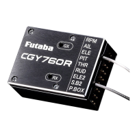
Terminal box
Hub
Hub
RPM Sensor
(1) RPM (Revolution sensor):
• Connect the revolution sensor.
(2) AIL Output:
• Connect the aileron (roll) servo.
(3) ELE Output:
• Connect the elevator (pitch) servo.
(4) PIT Output:
• Connect the pitch (collective pitch) servo.
(6) RUD Output:
• Connect the rudder (yaw) servo.
(7) ELE2 Output:
• Connect the second elevator servo.
(Swash mode: H4-XX)
(8) S.B2 Output:
• Connect the S.BUS2 tool.
(5) THR Output:
• Connect the throttle servo.
• Connect the ESC w/BEC and set the operation mode
to Gyro+THR mode.
*This diagram shows the various connections between the CGY760R and
receiver, servo, or sensors.
*S.BUS2 is a system that supports bidirectional communication from a
telemetry sensor to a receiver by extending the conventional S.BUS. Telem-
etry sensor(s), etc., are connected to S.BUS2 connector and used. S.BUS
compatible servo(s), etc., can not be used with S.BUS 2 connector terminal.
Connect the receiver battery (3.5 to 8.4 V)
to one of the "AIL" to "S.B2" connectors
other than "RPM" and "P.BOX".
(Do not connect to "RPM" and "P.BOX".)
 Loading...