EasyManua.ls Logo

FUTABA PK-FSM2.4G User Manual

FUTABA PK-FSM2.4G
2 pages
To Next Page IconTo Next Page
Page #1 background imageLoading...
Page #1 background image
No part of this manual may be reproduced in any form without prior permission.
The contents of this manual are subject to change without prior notice.
This manual has been carefully written. Please write to Futaba if you feel that any corrections
or clarications should be made.
Before using your new 2.4GHz system, please read this manual thoroughly and use the
system properly and safely. After reading this manual, store it in a safe place.
1M23N17303
Contents and Technical Specications
Your 2.4GHz system includes the following components;
Installing the PK-FSM2.4G/R603FS
[Specication]
Communication method: One-way operation system
Mode: PPM, HRS (Auto-detect)
Maximum operating range: 80m (Optimum condition)
For safety: F/S, B-F/S, ID (About 4billion ways of pair identi-
cations)
PK-FSM2.4G;
Transmission antenna: 1/2λ mono-pole
R603FS;
Reception antenna: Diversity type (Two antennas: internal
and external)
Power requirement: 6V Nicd battery
DSC function available
RS232C port: (for factory use only)
Size: 39x26x14mm (excluding a projection part)
Weight: 14.1g
PK-FSM2.4G Module
2.4GHz System
PK-FSM2.4G Module and
R603FS Receiver
Thank you for purchasing a PK-FSM2.4G module and an R603FS receiver. This system is
based on the combination of the newly developed 2.4GHz module and its correspondent
receiver. The system utilizes the 2.4GHz-SS radio communication and an ultra small antenna.
In addition, the system inherits Futaba's unique HRS (High Response System).
Features
2.4GHzSS (Spread Spectrum) radio communication system
Frequency channel setting unnecessary: Sifting the channels within the 2.4GHz band
automatically, this system minimizes the interference from other 2.4GHz system.
Accepts no unwanted signals by using ID code
The function “Auto-Detect” is utilized to automatically determine which mode is active,
HRS or PPM mode. (R603FS)
Short and small antenna (PK-FSM2.4G)/Diversity antenna (R603FS)
Applicable system; T3PK or T3VC Transmitter
R603FS Receiver
Module Cover for T3PK
Mini screwdriver
Install and adjust the PK-FSM2.4G module and R603FS receiver as described below.
Attachment of the module
󾻯
CAUTION
󾻫
Be sure to turn off the power of the transmitter before you attach
or detach the module.
1
Insert the module with care so that the connector pins of the
transmitter won't be bent.
󾻯
WARNING
󾻫
Adjust the antenna vertically to the ground. Otherwise, the oper-
ating range may become shorter.
T3PK Transmitter
PK-FSM2.4G Module
Antenna
Module Cover
T3VC Transmitter
PK-FSM2.4G Module
Antenna
0
1
2
3
4
5
6
7
8
9
(Antenna Moving Range)
0
1
2
3
4
5
6
7
8
9
I
NSTRUCTION
M
ANUAL
For cars only
Question and Answer IconNeed help?

Do you have a question about the FUTABA PK-FSM2.4G and is the answer not in the manual?

FUTABA PK-FSM2.4G Specifications

General IconGeneral
BrandFUTABA
ModelPK-FSM2.4G
CategoryConference System
LanguageEnglish

Summary

Futaba 2.4GHz System Features

2.4GHz System Description

System utilizes 2.4GHz-SS radio communication with ultra-small antenna and HRS technology for minimized interference.

Applicable Transmitter Systems

System is compatible with T3PK or T3VC transmitters, enabling use with specific Futaba models.

Contents and Technical Specifications

System Components Overview

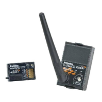
Lists the included components: PK-FSM2.4G module, R603FS receiver, module cover, and mini screwdriver.

System Specifications Details

Details communication method, range, safety features, antenna types, power requirements, and physical dimensions.

Installing the PK-FSM2.4G/R603FS Module

Module Attachment Procedure

Guidance on attaching the PK-FSM2.4G module to the transmitter, emphasizing power-off safety and connector pin care.

Receiver Installation and Setup

Antenna Installation Guidelines

Crucial warnings for optimal range: install antenna high, avoid cutting, keep away from noise, and protect it in a tube.

Coaxial Cable Handling

Warning against bending the coaxial cable of the antenna, as it can cause damage and affect performance.

Receiver Protection Advice

Recommendation to protect the receiver from vibration using soft material and use a waterproof bag if exposed to moisture.

Operational Conditions Caution

Cautionary note on using a 6V NiCd battery for power and 6V Futaba Digital Servo for HRS mode to ensure proper control.

System Power On Procedure

Step 1: Proximity Alignment

Step 1: Bring the transmitter and receiver within one meter of each other before powering on.

Step 2: Transmitter Power On

Step 2: Turn on the transmitter. Check the LED on the module for status indicators (Red/Green On/Blink).

Step 3: Receiver Power On

Step 3: Turn on the receiver. Check the LED on the receiver for status indicators (No signal, Receiving, ID unmatched, Failure).

Step 4: Receiver Tactile Switch

Step 4: Push the tactile switch on the receiver to confirm signal reception and ID matching.

Frequency Range Setting

Frequency Range Selection

Use rotary switches on the module to select the frequency range mode according to country regulations (e.g., GENERAL or FRANCE).

Fail Safe Function Setup

F/S Position Setting (PPM Mode)

In PPM mode, set F/S by moving the throttle trigger/stick to the desired position and pushing the module's tactile switch.

Battery F/S Functionality

Battery F/S activates when receiver voltage drops below 4.75V, moving the throttle servo to a preset position.

Related product manuals