- 2 - - 3 -
Attachment of the Module
CAUTION
Besuretoturnothetransmitter’spowerbeforeinstallingthe
module.
1
InstalltheTM-18withthetransmitterpoweredo.
2
Turnon the powerswitch ofthe transmitter. Atrst,
theTM-18'sLEDisoff.TurnontheCRSFfunction
ofthe transmitter. (Referto theinstruction manual of the
transmitterforhowtosettheCRSFfunction.TheT32MZhas
theCRSFfunctionasstandard.)TheTM-18LEDlightsupin
redandthenturnsgreen.
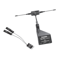
About module antenna
Theantennahasdirectivity.Thestrengthoftheradiowaveismaximum
inthelateraldirectionoftheantennaandminimuminthetipdirection
oftheantenna.Thereforepleasedonotpointtheantenna'stiptothe
aircraftasmuchaspossible.
*PleasekeepbothantennaofTM18and2.4GHz'sawayeachotherasfar
aspossible.
WARNING
Neverholdtheantennaduringflight.Also,donotattach
conductiveobjectssuchasmetaltotheantenna.
*Cannot be controlled due to lower transmission output.
How to Link
EachTM-18 RFtransmittermodulehasanindividually
assigneduniqueIDcode,andthereceivermustbe
linkedtotherespectiveTM-18'sIDcodetostartthe
operation.Oncethelinkingisdone,theIDcodeisstored
in the receiver, and re-linking is unnecessary unless the
receiveristobeusedwithadierentTM-18RFmodule.
Additionally,itisessentialtonotethatthefactoryhas
alreadylinkedthisTM-18 andR9001SBreceiverset.
Shouldyouwishtore-linkthem,orifyouhavepurchased
aseparatereceiverandwouldliketolinkittothisTM-18,
pleaseadheretothefollowingprocedure.
WARNING
Donotperformlinkingwhilethemotorisconnectedorthe
engineisrunning.Itishazardousifthemotorsuddenlyrotatesor
theengineblowsup.
Afterthelinkingisdone,pleasecyclereceiverpowerand
checkifthereceivertobelinkedisreallyunderthecontrolbythe
transmittertobelinked.
1
AfterinstallingtheTM-18RFmoduleonthetransmitter
body,turnonthetransmitter'spower.
2
WhentheTM-18LEDchangesfromredtogreen,and
youcan confirm that it is ready foroperation,press
thetactswitchontheTM-18forabout3secondsand
releasethetact switchwhenthegreenLEDblinksonce.The
greenLEDwillstartblinkingandwillbeinlinkmodefor30
seconds.(OntheTM-18,ifyoupressthetact switchonce
againduringlinkmode,itwillextendthelinkmodefor30
secondsfromthatpoint.)
3
Bringthereceiverwithin50cmandturnonthereceiver
power.Afterturningon the receiver'spower,itwill be
inthelinkwaitingstateabout3secondslater.
4
ThelinkiscompletewhentheLEDonthereceiver
turnsfromredtogreen.(Thereceiverwillkeepthelink
waitingstateabout3seconds.)
LED display of R9001SB receiver
Green Red Status
O On No signal reception
On O Receiving signals
Alternate blink
Unrecoverable error (EEPROM, etc.)
If cycling the power but no recovery, please contact
Futaba Service Center.
Receiver Installation
YouwillnotethattheR9001SBdiffersinappearance
fromthestandardFutabareceiver.
Antenna
Antenna
TheR9001SBincorporatestwoseparateantennasinto
itsdesign,enablingittoreceiveradiotransmissionattwo
positions.
Futaba'sdualantennadiversity,orDAD,seamlessly
selectsthebestsignalreceptionbetweentheseantennas
tokeepthesolidlinkwiththetransmitter.
Toobtainthebestresultsfromthe R9001SB receiver,
pleaserefertothefollowinginstructionsandprecautions:
1
Wrapthereceiverwithfoamrubbertopreventitfrom
beingaectedbyvibrations.
2
Ensurethatthetworeceiverantennasarekeptat.Do
notfoldorbendthemtogetbestreception.
3
Ifpossible,pleaseensurethatthe twoantennasare
placed90degreeseachother.Pleasenote:Thisisnota
criticalgure.However,themostimportantthingistokeep
theantennasawayfromeachotherasmuchaspossible.
4
If there aresomeconductive materialsclosetothe
antenna,itmaydegradethequalityoftheRFlink.
Pleasekeeptheantennaawayfromthesuchmaterials.
5
Ensure that the antennas are at least 1/2" away from
conductivematerialssuchasmetalandcarbon.Please
note:thatthisdoesnotapplytothecoaxialportionofthe
antenna.It is essential, however, not to bendthe coax or
antennainatightradius.
6
If the fuselage ismade of conductive materialssuch
asmetalandcarbon,theantennaportionMUSTbe
positioned outside of the fuselage. Additionally, please do
notattach theantennaitselftothisfuselage asmentioned
above#4.
*Forexample,manytypesofglidersusecarbonfuselage.Wheninstalling
thereceiverintosuchmodels,theantennaprecautionsmustbestrictly
adheredto.
WARNING
Beverycarefulwhenhandlingthereceiverantennas.Repeated
bendingandflexingoftheantennasorexcessiveforcecould
weakenorcompromisetheinternalantennaconnections.
Keeptheantennasawayfromthemotor,ESC,andothernoise
sourcesasmuchaspossible.
Anntenna
Anntenna
The primary purpose of the Illustration is to demonstrate how the
antennashouldbeplaced.Foractualinstallation,thereceivermust
bewrappedwithaspongeorplacedwithoatingmaterialtoprotect
itfromvibration.Thereceivercontainsdelicateelectronicpartsand
shouldbeprotectedfromvibration,shock,andseveretemperature
exposition.
*Thereceiverdoesnothaveamoisture-proofandwaterproof
function.
Oncethemoistureenterintothereceiver,itmaycausethe
intermittentoperationor failure.Therefore, wesuggest wrapping
thereceiverinaplasticbagorsimilarprotectivecovering.
Thiswillalso protectthereceiver fromfuel orexhaustresidue that
willleakintothefuselage.
ByusingFutabaAdRCSS900MHzandFutaba2.4GHz
systemtogetherwillprovidethebettersecureRFlink.
Setting of the F/S (Failsafe) modeSetting of the F/S (Failsafe) mode
InthecombinationofTM-18andR9001SB,theF/S
functioncanbesetonlyforthe3rdchannel(throttle).For
safety,werecommendusingtheF/Sfunction.
F/S mode
●HOLD:Inthesignalloss,theHOLDmodeholdsthe
throttleservoinitslastcommandedposition.(TheRF
output confirmationdisplayofthetransmitterusually
lights.)
●F/S:Inthe signal loss,the F/S modeholds the throttle
servoinitslastcommandedpositionforonesecondand
thenmovesittoapredeterminedposition.
CAUTION
DonotpressthetactSWduringtheflightasthemodulewill
beinrangecheckmodesothattheRFpowerwillbeloweredand
willresultinfatalcrash.
*TheTM-18+R9001SB(900MHz)canonlysetfail-safefor3CH(throttle).
*Setonly3CH(throttle)forfail-safeonthe2.4GHzside.
*Setthefail-safepositionofeach900MHz/2.4GHztothesameposition.
Dierentfailsafesettingsmaycausetheservotobehaveunexpectedly.
*For FDLS-1/DLPH-1, etc., ittakes about 10 secondsto memorize the
fail-safe position. Wait 10 seconds after turning on the power before
startingtheight.
CH3 (throttle) F/S operation mode selection and
F/S position setting
<HOLD
CH3-F/S mode switching method>
1
Turnonthepowerswitchofthetransmitter,andchecktheRF
output is activated. (The LED of TM-18 will turn green from
red.)Checkthatbeforepoweringonthereceiver.
2
Movethe throttle stickonthetransmittertotheslow
positionandpressthetact switchonthereceiverfor
about3seconds.Release thetact switchwhentheLED
turnso.TheLEDlightsupred/greenatthesametime.
3
At thistime,theHOLDmode CH3-F/Smodeis
switched.WhenswitchingfromHOLDmodetoCH3-F/
Smode,theCH3(throttle)F/Spositionisset.
4
WhentheLEDonthereceivergoesfromred/green
simultaneouslightingto green lighting, itreturnsto
theusualreceptionstate.
Installing the TM-18 RF Module and R9001SB ReceiverInstalling the TM-18 RF Module and R9001SB Receiver
* In the case of T32MZ, attach the included mounting parts
and double-sided tape as shown in the gure.
*Connect between TM-18 and the transmitter via CRSF
connection cable which come with this set. For T32MZ, use
CRSF port. For T16IZ(S), T18SZ, and T12K, use S.I/F port.
*Aligntheclawsofthe
mounting parts with the
threegroovesonthe
TM-18andattachit.
*Attachdouble-sided
tape.
Double-
sided
tape
Mounting
parts
* As shown in the gure, attach the included double-sided
tape, and connect the CRSF port of the TM-18 and the
S.I/F connector of the transmitter with the CRSF signal
connection cable. (Example: T16IZ)
Double-sided
tape
CRSFsignal
connectioncable
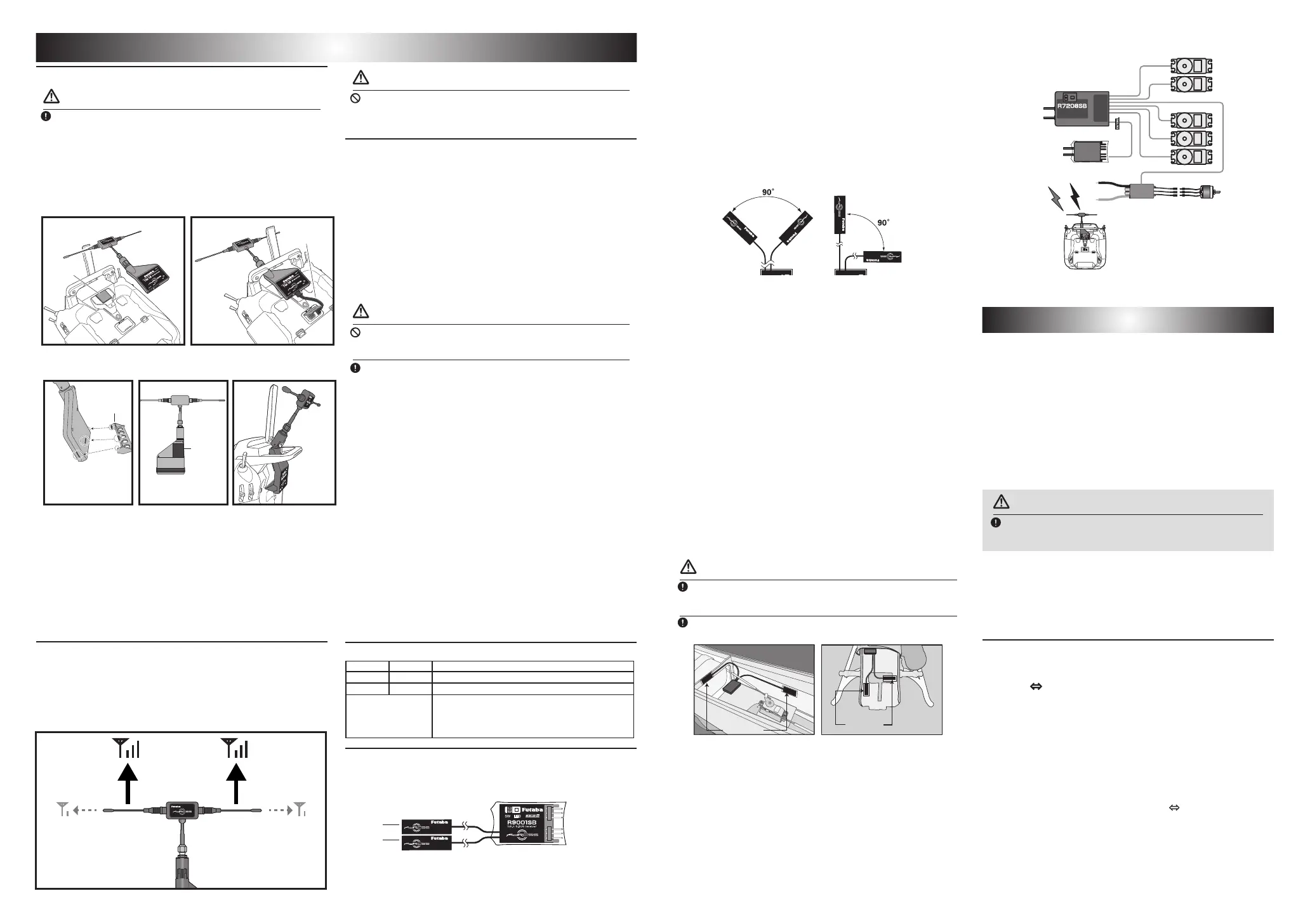
2.4GHz R7208SB
900MHz R9001SB
ESC
2.4GHz
TM-18
900MHz
 Loading...