51834265_V_1_2.DOC
18/41
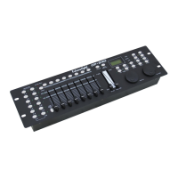
5.3 DMX-512 connection with the projector
The wires must not come into contact with each other, otherwise
the fixtures will not work at all, or will not work properly.
Only use a stereo shielded cable and 3-pin XLR-plugs and connectors in order to connect the controller with
the fixture or one fixture with another.
Occupation of the XLR-connection:
You can adjust the XLR polarity via the DMX POLARITY selector.
Building a serial DMX-chain:
Connect the DMX-output of the CP-240 with the DMX-input of the nearest projector. Always connect one
output with the input of the next fixture until all fixtures are connected.
Caution: At the last fixture, the DMX-cable has to be terminated with a terminator. Solder a 120
Ω resistor
between Signal (–) and Signal (+) into a 3-pin XLR-plug and plug it in the DMX-output of the last fixture.
Projector addressing
Please note that the CP-240 assigns the DMX-starting addresses every 16 steps. You have to address every
projector to the respective starting address. Otherwise, the channel assignment will not be correct. All
projectors with the same starting address work synchronically.
Projector Starting address Projector Starting address Projector Starting address
Projector 1 1 Projector 5 81 Projector 9 161
Projector 2 21 Projector 6 101 Projector 10 181
Projector 3 41 Projector 7 121 Projector 11 201
Projector 4 61 Projector 8 141 Projector 12 221
5.4 Assigning the DMX-channels
All channels can freely be assigned.
1) Press Fine + Mode buttons until the Assign-LED is lit.
2) Select the desired projector with the projector select buttons.
3) Adjust the Fade Time fader to select the control channel of the controller. E.g. X or Y.
4) Adjust the Speed fader to select the respective projector channel. E.g. Channel 1 or 2.
5) Press the Rec-button.
6) To set channel 19 and 20, press Page Select button, the Page B LED will be lit. Then repeat step 3 to 5.
Example 1: Assign projector channel 1 to PAN-encoder.
Adjust the Fade Time-Fader to X. Adjust the Speedfader to 1. Press the Rec-button. The projector's PAN-
movement can now be controlled via the PAN-encoder ansteuern.
Example 2: Assign projector channel 3 to control-channel 1.
Adjust the Fade Time-Fader to 1. Adjust the Speedfader to 3. Press the Rec-button. Projector channel 3
(e.g. color-wheel) can now be controlled via channel-fader 1.
Example 3: Assign projector channel 2 dem TILT-Encoder zuweisen.
Adjust the Fade Time-Fader to Y. Adjust the Speedfader to 2. Press the Rec-button. The projector's TILT-
movement can now be controlled via the TILT-encoder ansteuern.
Example 4: Assign projector channel 4 to control-channel 2.
Adjust the Fade Time-Fader to 2. Adjust the Speedfader to 4. Press the Rec-button. Projector channel 4
(e.g. gobo-wheel) can now be controlled via channel-fader 2.
7) Press the Fine and Mode-button so that the Assign-LED shuts off.