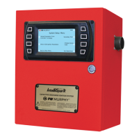
Section 40 00-02-0893
2014-07-18 - 6 -
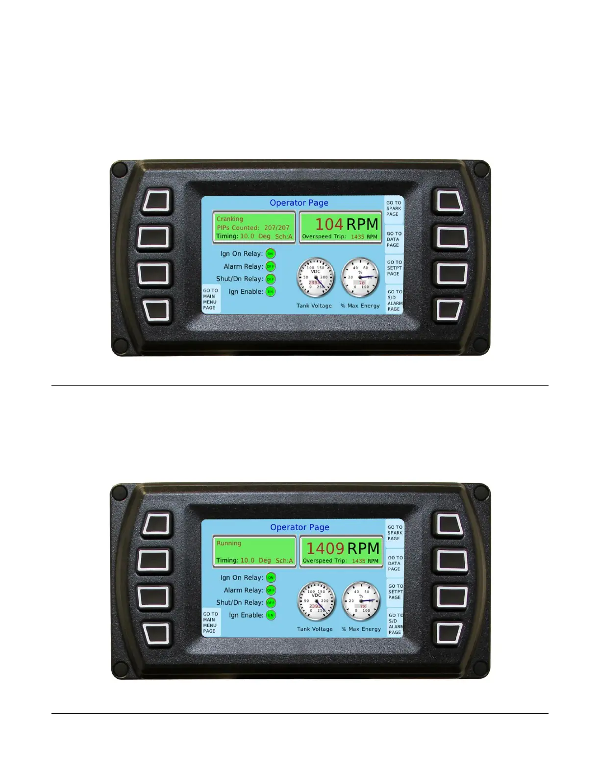
Figure 3.0 shows the page contents during a typical cranking phase.
For this example, the PIP count is perfect at 207 teeth counted out of 207 programmed. The
Ign On Relay LED is green indicating that it is firing the coil drivers and that the relay is on.
When this relay turns on the fuel valve, the engine should start to pick up speed.
Figure 3.0 Cranking
Engine Run Mode
Once the engine RPM exceeds the Crank/Run RPM, the system will go into the normal run
mode. Once there, the system will use different tolerances on the PIP count, typically the
tolerance is tightened. The user has some latitude to change these tolerances, but the system
also has limits that cannot be exceeded. Figure 4.0 shows the contents during a typical run
mode.
Figure 4.0 Normal Running