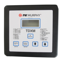
The TDXM-DC is an innovative and configurable temperature scanner/pyrometer designed for monitoring temperatures in various applications. It features a robust design with a built-in power supply, making it a versatile solution for industrial environments. The device is equipped with a 7-character, 7-segment Liquid Crystal Display (LCD) that presents easy-to-read characters, ensuring clear visibility of temperature readings and other information. For user interaction and configuration, the TDXM-DC incorporates a 5-button membrane keypad on its faceplate.
Function Description
The primary function of the TDXM-DC is to scan and monitor temperatures from multiple thermocouples. It supports up to 24 type J or K thermocouples, which can be either grounded or ungrounded. Each of these 24 channels is independently configurable, allowing users to select the thermocouple type (J or K) and the desired temperature units (°F or °C) for readout. This flexibility ensures compatibility with a wide range of temperature sensors and measurement standards. Unused channels can be set to "Ignore," preventing them from being displayed or affecting the device's outputs, provided a jumper is installed on these channels.
Beyond simple temperature scanning, the TDXM-DC offers advanced control options through its three outputs. Two of these outputs are Field Effect Transistors (FETs), and one is a Form-C Relay. Each channel has three adjustable setpoints (SP1, SP2, and SP3), which correspond directly to these outputs. This allows for flexible system integration, where different sets of channels can be grouped to trigger specific outputs, enabling various alarm or shutdown functionalities.
A key feature of the TDXM-DC is its ability to monitor and alarm or shut down based on deviation from an average temperature. This is particularly useful for applications like engine exhaust temperature monitoring or bearing temperature surveillance, where maintaining consistent temperatures across multiple points is critical. The device can handle up to two groups of temperatures for deviation monitoring (GRP/DEV). If any channel within a defined group deviates from the average by a user-specified amount, the corresponding output (SP1 for the first group, SP2 for the second) will be energized. The deviation value is displayed as an absolute value in the SP History.
The TDXM-DC also includes a built-in RS485 serial communications port, enabling it to communicate with external controllers, PLCs, computers, or SCADA systems using the MODBUS RTU slave protocol. This allows for remote monitoring, data logging, and control of the device. The baud rate, number of stop bits, and slave node number can all be configured via the keypad. For daisy-chain configurations, a termination resistor (customer supplied) is recommended if the TDXM-DC is the last device in the chain.
Usage Features
The user interface of the TDXM-DC is designed for straightforward operation and configuration. The LCD displays current temperature readings, setup menus, and historical data.
- Normal Scan Mode: In this mode, the device cycles through each configured channel, displaying its temperature for a user-defined duration (default is 3 seconds). The sequence repeats after all channels have been displayed. This mode can be toggled ON or OFF by pressing and holding the SCROLL button.
- Locked Scan Mode: Users can temporarily interrupt the normal scan by using the UP or DOWN buttons to select and lock a specific channel for 60 seconds. During this time, only the locked channel's temperature is displayed. All channels continue to be scanned and checked against setpoints in the background. Pressing the SCROLL button unlocks the channel and resumes normal scan.
- Setpoint History: The TDXM-DC stores the last setpoint trip for each output in non-volatile memory. By pressing the SP HISTORY button, users can view which channel and setpoint (SP1, SP2, or SP3) caused the last trip. If a group/deviation function caused the trip, the display will show the offending channel and the absolute value of the temperature deviation.
- Setup Menus: Configuration of the TDXM-DC is done through a series of setup menus accessed by simultaneously pressing and holding the SCROLL ENTER and CHANNEL SP1-3 buttons for 5 seconds. A passcode is required to enter these menus, ensuring security. Within the setup menus, users can:
- Configure TC Type/Units (Setup 1): Individually set each of the 24 channels for J or K type thermocouples and °F or °C units. Unused channels can be ignored.
- Adjust Offset (Setup 2): Apply an offset from -20 to +20 units (°F or °C) to each channel's temperature reading to match other instrumentation.
- Set Setpoints (Setup 3): Define three setpoints (SP1, SP2, SP3) for each channel. Setting a setpoint to zero disables the corresponding output for that channel. This allows for grouping channels and implementing alarm/shutdown sequences.
- Configure Group/Deviation (Setup 4): Define up to two groups of channels for deviation from average calculations. Users specify the number of channels in each group, the allowable deviation, and an enabling temperature setpoint and channel.
- Set CH Scan Delay (Setup 5): Adjust the display delay between channels during normal scan (0-10 seconds).
- CJ Display Selection (Setup 6): Choose whether to display cold junction temperature in °F or °C, or disable its display.
- Configure RTU/Baud (Setup 7): Set the RTU Node address (0-255) and select the baud rate and stop bits for RS485 communication.
- Set Unit Number (Setup 8): Assign a prefix (0-99) and suffix (0-9999) to the unit for identification, which is available via MODBUS registers.
- SP3 Latch (Special Version): A special version of the TDXM-DC allows SP3 to latch upon a trip detection. The SP3 output remains active until manually reset or power is recycled. The display indicates the latched status. Resetting requires simultaneously pressing and holding SCROLL ENTER and DOWN ARROW keys for at least 3 seconds.
Maintenance Features
The TDXM-DC is designed for reliability, but certain aspects are important for maintaining its performance and troubleshooting potential issues:
- Wiring Practices: Proper wiring is crucial. Shielded thermocouple leads are recommended, and drain wires should be connected to the "TC SHIELD" input terminal or chassis ground, ensuring they are ungrounded when connected to the "TC SHIELD" input. Thermocouple leads should always be routed separately from other wiring to prevent interference.
- Troubleshooting Tips: The manual provides a comprehensive troubleshooting guide for incorrect temperature readings or device malfunctions. This includes checking:
- Correct TC Type and Units settings.
- Reasonableness of cold junction readings.
- Functionality with a jumper in place of the TC (should read cold junction temperature).
- Proper wiring practices, including the use of shielded thermocouple grade extension wire, absence of splices involving non-TC type metals, and separation of TC wires from other wiring.
- Potential grounded thermocouple problems.
- DC power voltage for proper range and noise.
- Error Codes: The device displays specific error codes for grouping conflicts (e.g., "Channel 1 disabled," "Too few channels," "Inconsistent engineering units," "Channels skipped/disabled," "Deviation value set to 0," "Group size goes past the 24th channel").
- CJ Error: If the cold junction sensor fails, the display will show "CJError," output SP3 will de-energize, and SP1/SP2 will turn on. The SP1, SP2, and SP3 histories will show "61." In this state, the TDXM-DC will cease scanning channels and the keypad will be unusable, indicating a need for unit replacement.
- Watchdog Error: An internal processor or hardware failure will cause the display to show "60." Similar to a CJ Error, the unit will stop scanning and the keypad will be unusable, necessitating replacement.
- Replacement Parts: A terminal plug replacement kit (P/N 10-00-7848) is available for maintenance.
- Mounting: For outdoor use, the TDXM-DC controller must be mounted within a weatherproof enclosure to protect it from environmental elements. The mounting process involves precutting a square hole and four mounting holes, aligning studs, and securing with washers and nuts, ensuring not to overtighten.