sect. 50 00-02-1010
rev. 2021/07/21
Fender washer
with star nut
on top stud
(option)
5/16” star nuts on three studs
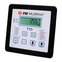
How to Replace LCDT with TTD
In this LCDT replacement conguration, the TTD will not carry a NEMA 4 rating due to the mounting stud removal mentioned in
the installation section below.
Hazardous Area Classification
The TTD has CSA Class I, Division 2, Groups B, C and D approval. This differs from LCDT which has CSA Class I, Division 1,
Group D approval. Consult with your AHJ for a review of classication for the area where the LCDT is installed for verication
that it may t into Class I, Division 2 classication.
Certification
Please read the Installation & Operation manual for the TTD. This will familiarize you with the new features and congurability
available in the TTD.
LCDT mounting holes circled
Catalog Subsection for Table of Contents
95026 Product Name for Catalog Table of Contents
Remove the
circled TTD
mounting
studs.
Installation
1. The TTD-2 model (part # 50700601) offers exact drop-in
replacement option for both models of LCDT-NO and
LCDT-NC.
a. Systems powered by 12- or 24-VDC (battery powered)
or CD negative ground ignition are fully compatible.
b. Systems powered by 120-VAC line voltage will require
a 24-VDC power supply installed to power the TTD.
c. CD positive ground ignition systems are not supported
by TTD.
2. This guideline is for typical installations with fuel valve,
ignition and power input connection changes and are
meant to supplement the TTD installation diagram 50-08-
0718.
a. Refer to the drawing in the TTD Installation &
Operation manual for clarication on your specic
installation.
b. To nd all information about TTD features and options
as well as the downloadable installation & operations
manual, go to https://www.fwmurphy.com/products/
controllers/ttd.
3. Mount the TTD head.
a. Only three (3) of the TTD mounting studs are used to
mount to the original LCDT mounting holes.
b. On the TTD, remove the mounting studs (5) circled
below. Use pliers to turn them counterclockwise to
unscrew from the bezel. Removing studs in this matter
will not affect warranty of the TTD.
c. Align the TTD studs with the 2 bottom holes and insert
into the LCDT opening. They will t into the old holes.
The top center stud will be on the top edge of the
cutout.
d. Install a star nut on the bottom studs rst, then on
the top center stud. The top center nut will catch
the edge of the sub panel plate as shown below. For
vibration or stability concerns a 5/32” x 7/8” stainless
fender washer is recommended.
e. Tighten the three 5/16” star nuts to 9 in. lbs. (1 Nm).