10
T
he red LED on the front right hand side of the
charger will illuminate to indicate charging is in
progress. A green LED will illuminate when the battery
is fully charged.
Unplug the charger when not in use and store it in a
s
uitable storage cabinet.
Avoid charging your battery in freezing conditions as
c
harging power will not be sufficient.
W
hen charging more than one battery pack in
succession allow at least 30 minutes for the charger
to cool down before charging an additional battery.
Always remove the battery pack and store it safely
when the tool is not in use.
Caution: If at any point during the charging process
none of the LEDs are lit, remove the battery pack from
the charger to avoid damaging the product. DO NOT
insert another battery.
CHARGE STATUS
To display the amount of charge left in the battery,
press the charge level indicator button, Fig.2.
ASSEMBLY
Warning! To prevent accidental starting that could
cause serious personal injury, always remove the
battery pack from the product when assembling parts.
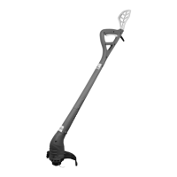
ATTACHING THE GUARD
Remove the battery pack. Invert the grass
trimmer/edger to access the trimmer head. Using a
Phillips head screwdriver, remove the pre-installed
s
crew from the trimmer head.
P
lace the guard on to the trimmer head so that the
l
arge part of the guard sits to the rear, Fig.3.
A
lign the screw hole on the guard with the screw hole
on the trimmer head. Insert the screw into the trimmer
head, fastening the guard in place, Fig.4.
Remove the protective tape from the line cutting
blade, Fig.5.
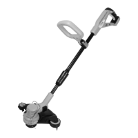
ADJUSTING THE AUXILIARY HANDLE
T
o avoid injury, adjust the auxiliary handle for
o
ptimum control and balance. Do not overreach when
operating grass trimmer/edger. Keep proper balance
at all times for better control of the tool in unexpected
situations.
The auxiliary handle can be moved either up and
down the shaft, forward and backwards or rotated
360º around the shaft. To find your optimum desired
position unlock the assist handle locking lever by
pulling outwards, Fig.6. Once you have the desired
position relock the assist handle locking lever by
pushing inwards.
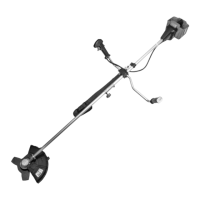
ADJUSTING THE SHAFT LENGTH
Loosen the lower part of the centre collar (Fig.7). This
will allow the lower part of the shaft to be extended or
retracted. When the shaft is at a comfortable length,
retighten the collar.
ROTATING THE SHAFT
The shaft can be rotated to the 0 or 180º position for
trimming and edging operations.
Pull the upper part of the centre collar (Fig.8). This will
allow the motor to be rotated between the 0 or 180º
position.
Note: The head will only lock in the 0 or 180º position.
ROTATING THE TRIMMER HEAD
The trimmer head can be rotated to the 0 or 90º
position for trimming and edging operations.
Press the Edger adjustment button, Fig.9, and the
trimmer head will spring around 90º. Make sure it is
locked into place. To move the trimmer head back
simply press the Edger adjustment button again and
rotate back to its original position.
EXTENDING THE LINE
To extend the line press the spool line extension
button on the spool, Fig.10.
Warning! To prevent accidental starting that could
cause serious personal injury, always remove the
battery pack from the product when extending the
line.
ADJUSTING THE LINE CUTTING BLADE
The cutting line can be set at two lengths (250 &
300mm). To adjust the line cutting blade turn the Line
cutting blade adjustment dial by pushing down and
rotating 180º, Fig.11.
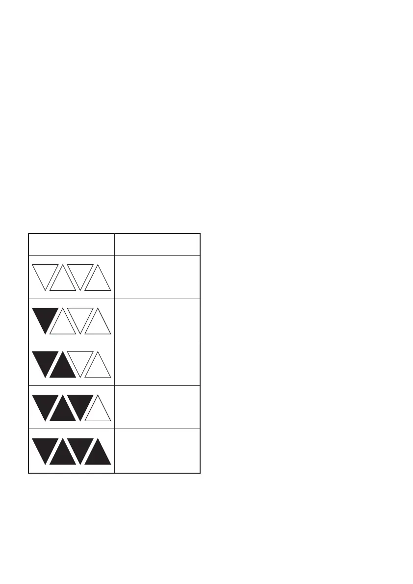
Charge level indicator Amount of charge
remaining
0-10%
10-25%
25-50%
50-75%
75-100%
 Loading...