15
P
lace the battery pack into the charger base.
(Note the battery has raised ribs which allows it to fit
into the charger only one way). Time the charge for
60/130 minutes only.
2,0 Ah -battery, charge for 60 minutes
4,0 Ah -battery, charge for 130 minutes
The red LED on the front right hand side of the
charger will illuminate to indicate charging is in
p
rogress. A green LED will illuminate when the battery
is fully charged.
U
nplug the charger when not in use and store it in a
suitable storage cabinet.
Avoid charging your battery in freezing conditions as
charging power will not be sufficient.
When charging more than one battery pack in
succession allow at least 30 minutes for the charger
to cool down before charging an additional battery.
Always remove the battery pack and store it safely
when the tool is not in use.
Caution: If at any point during the charging process
none of the LEDs are lit, remove the battery pack from
the charger to avoid damaging the product. DO NOT
insert another battery.
CHARGE STATUS
To display the amount of charge left in the battery,
press the charge level indicator button, Fig.2.
A
SSEMBLY
P
ACKAGING CONTENTS
•
Chainsaw
• Chain
• Guide bar
•
Guide bar cover
•
Operator’s manual
W
ARNING. If any parts are damaged or missing, do
not operate this product until the parts are replaced.
Use of this product with damaged or missing parts
c
ould result in serious personal injury.
WARNING. Do not install the batteries until assembly
is complete. Failure to comply could result in
accidental starting and possible serious personal
injury.
WARNING. Do not attempt to modify this product or
create accessories not recommended for use with this
product. Any such alteration or modification is misuse
and could result in a hazardous condition leading to
possible serious personal injury.
ASSEMBLING SAW CHAIN AND GUIDE BAR
CAUTION: Always be sure that the tool is switched off
and the battery cartridges are removed before
carrying out any work on the tool.
CAUTION: Do not touch the saw chain with bare
hands. Always wear gloves when handling the saw
chain.
NOTE: Make sure the chain brake is disengaged.
Disengage the chain brake by pulling it backward.
Place the chainsaw on a flat, stable surface. Unscrew
the guide bar locking knob anticlockwise and remove
the sprocket cover, Fig.3.
Put the chain on the guide bar considering the running
direction of the chain. The cutting teeth on the upper
side of the bar must point in forward direction, Fig.4.
Put the free end of the chain over the chain driving
wheel, Fig.5 (A).
Place the bar such that the long hole in the bar is
placed exactly on the guiding element, Fig.5 (B), in the
bar seat.
Check whether all chain links are seated exactly in the
bar’s groove and the chain is lead around the chain
driving wheel correctly.
Put the cover back on and push it in place.
Moderately tighten the guide bar locking knob by
turning it clockwise.
Tension the chain. To do so tighten the guide bar
locking knob. The chain should be tensioned such
that it can be lifted by about 3-4mm in the centre of
the guide bar (Fig.6) (6.1). To decrease the chain
tension turn the guide bar locking knob anticlockwise.
Note: The guide bar may need to be held horizontally
to properly tighten the chain.
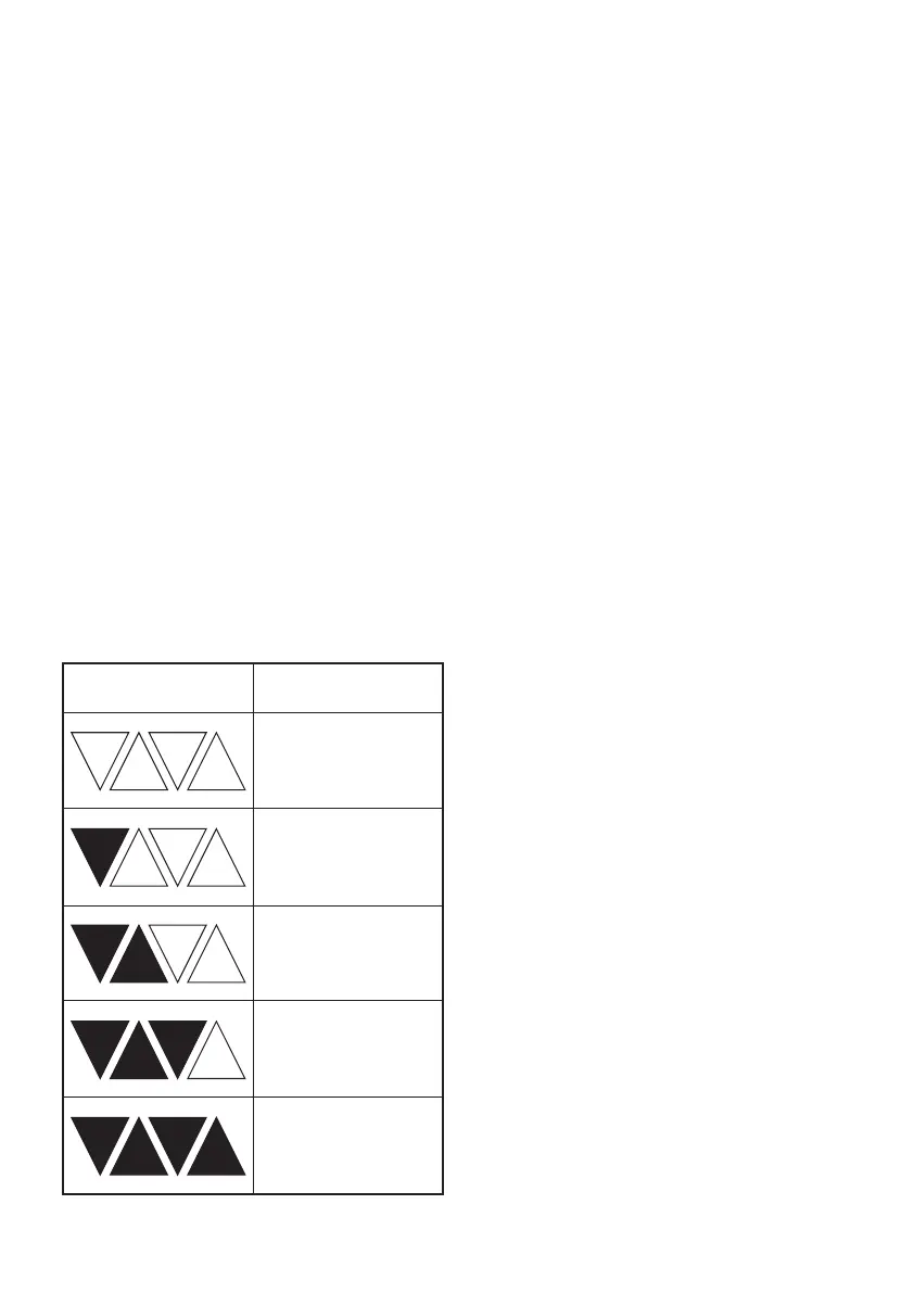
Charge level indicator Amount of charge
remaining
0-10%
10-25%
25-50%
50-75%
75-100%
 Loading...