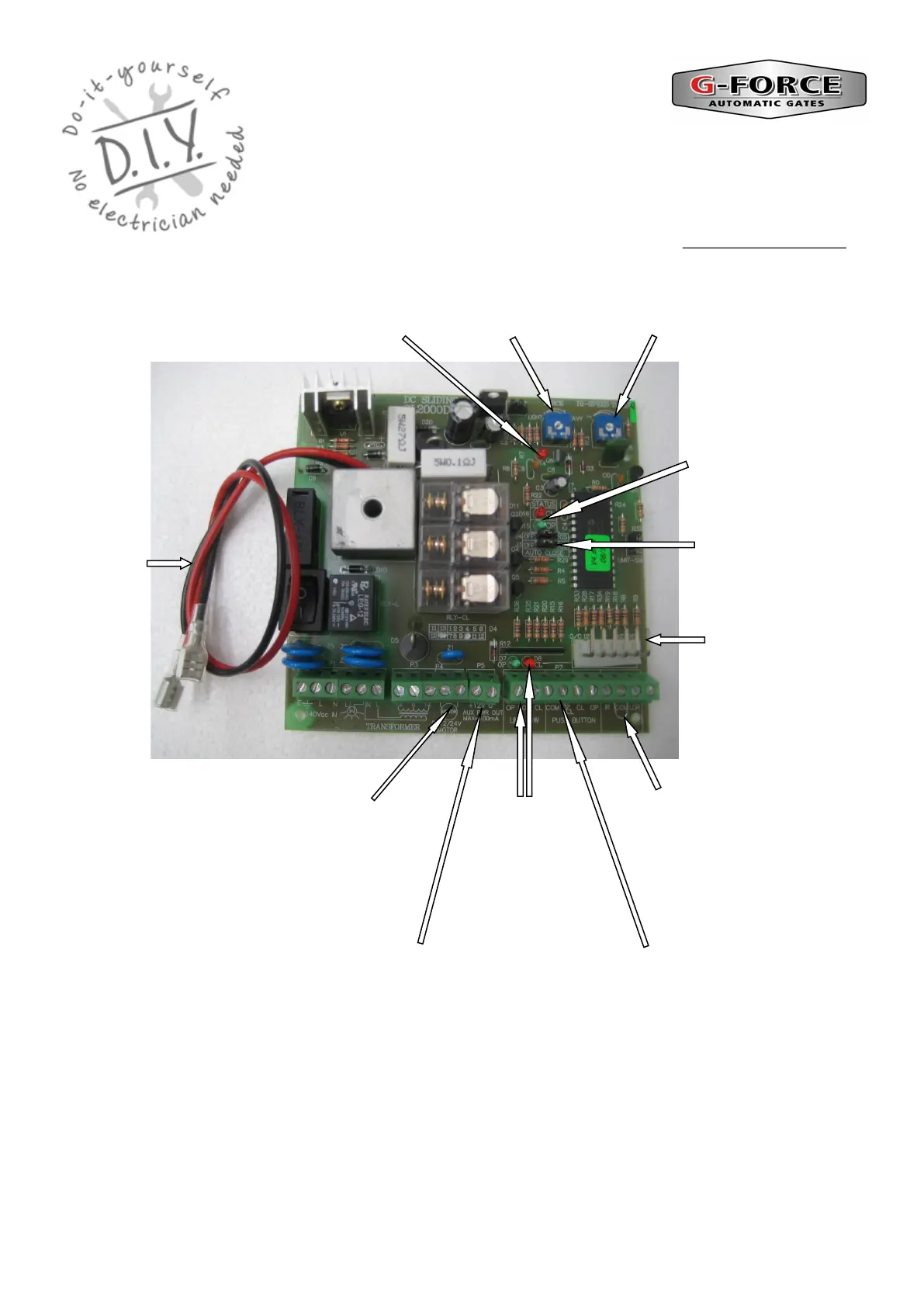
SL 2000 Circuit Board
Data Sheet
DIY Automatic Gate Kits
Solar & Low Voltage Specialists
PH 1800 111 930
info@gforceautogates.com.au
www.gforceautogates.com.au
High Speed Timer—
Should be set to zero
Green—Open LED
Red—Close LED
Plug On Pins for
plug on Receiver
Wire in Receiver / Push Button Trigger
Terminals—Connect wires to “COM” and
OP/CL
Low Motor
Force LED
Wire in Receiver / Accessory Power Connection Terminals
“+12V” positive terminal / “0” Negative terminal
Motor Force
Trim Pot
PE Beam ‘Terminals
(Remove link wire when
connecting Safety Beams)
Battery
leads
RED
Positive /
BLACK
Negative
DC 12/24V
Motor Wire
Terminals
Limit
Switch
Terminals
and LED’s
Auto Close OFF / ON /
TIME function selection
“Jumpers”