Do you have a question about the G-WAVE Solutions BDA-PS7W-37 and is the answer not in the manual?
Denotes protective ground terminal importance and proper usage of power cord.
Warns about dangerous voltages and advises terminating RF connectors before power application.
States maintenance must be by qualified personnel and warns of internal component danger.
Details FCC ERP limit and required antenna separation distance for compliance.
Specifies antenna separation distances for IC RF exposure compliance based on antenna gain.
Details frequency ranges, gain, noise figure, output power, and impedance.
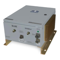
Lists size, RF connectors, and weight of the amplifier unit.
Monitors for oscillation and shuts down amplifiers to prevent interference.
Important warning for FCC licensees and qualified installers regarding legal operation.
Critical instruction to connect all cables before applying AC power to prevent damage.
Specifies required antenna isolation to prevent gain ripple and oscillations.
Guides proper connection of donor and service antennas to respective BDA ports.
Explains how to adjust BDA gain by reducing attenuation in 2 dB steps.
Describes the ALC feedback loop for minimizing intermodulation and limiting output power.
Step-by-step guide for setting Uplink and Downlink gain using ALC LEDs.
Warning against operating with input signal levels above -30 dBm to prevent damage.
Discusses recommended isolation and factors affecting it to prevent BDA oscillation.
Provides analytical equations for calculating horizontal and vertical antenna isolation.
| Brand | G-WAVE Solutions |
|---|---|
| Model | BDA-PS7W-37 |
| Category | Amplifier |
| Language | English |