Do you have a question about the G-Wave BDA-PS8NEPS-20/20-70-M and is the answer not in the manual?
Review manual and ensure compatibility with amplifier specifications for safe operation.
Explains the symbol denoting important safety instructions and the equipment's suitability for RF applications.
Describes the protective ground symbol and its importance for equipment safety and grounding.
Identifies dangerous voltages present on the equipment and advises extreme caution during handling.
Highlights the symbol for ESD-sensitive devices and the need for proper handling protection.
States that maintenance must be performed by qualified personnel only due to potential danger.
Warns against blocking air inlets/outlets to prevent amplifier damage from overheating.
States the product's Class B device status and compliance with FCC Part 90 and Part 24 requirements.
Confirms compliance with Industry Canada (IC) RF Exposure Requirements pursuant to IC RSS-131.
Clarifies that rated output power is for single carrier; multi-carrier reduces rating by 3.5 dB.
Advises minimum separation distance between antenna, booster, and user for RF safety.
Explains ALC for output power limiting and the variable step attenuator function.
Describes the Mini-BDA's use as a line amplifier with an optional external bias-tee.
Details operating temperature and airflow requirements for standard indoor use.
States indoor units are not designed for outdoor use or enclosures, which can cause damage.
Warns against using unstable power sources like generators, as it voids the warranty.
Standard feature with local LED lights indicating various failures.
Option for powered DC only at +28 VDC.
Option for AC Surge Protection and DC Line Conditioning, required if powered by generator.
9-Pin connector for remote alarming via dry contact for amplifier failures.
The BDA uses an external power supply connected via a single pin 15V DC input.
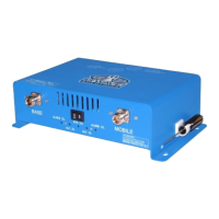
RF connections are made via two Type 'N' female connectors labeled 'BASE' and 'MOBILE'.
Advises isolation between antennas should be 15 dB higher than BDA gain to prevent oscillations.
Mount the BDA on the wall with RF connectors pointing DOWN using appropriate screws.
Ensure isolation between donor and service antennas is at least 15 dB greater than BDA gain.
Connect the donor antenna to 'BASE' and service antennas to 'MOBILE' connectors.
Verify both attenuators are set to maximum (30 dB) on the front panel.
Connect power cord and verify the 'Power ON' lamp is illuminated.
Warns that the device is not for consumer use and requires FCC/ISED licenses or consent.
Explains the ALC feedback loop for sensing and limiting output power to a factory preset level.
Step-by-step guide for setting gain on Uplink/Downlink paths using attenuation and LEDs.
Warns that operating at max gain with > -30 dBm input can damage the BDA.
Summarizes conditions for ALC, Uplink/Downlink, Donor, and Mobile alarms.
Describes how gain is reduced by up to 30 dB in 2 dB steps via rotary switches.
Explains how to determine BDA gain by subtracting attenuation from the reported gain.
A matrix showing different alarm conditions and their corresponding LED indicators.
Amplifiers ship with 30 dB attenuation to prevent overdrive of the ALC limitation.
Step-by-step process to adjust gain by turning back the rotary switch until ALC LED turns on.
Warning that input signal level greater than -30 dBm may cause system damage.
Describes the AC Power LED illumination and field test for power supply status.
Describes DL Alarm LED illumination for DL amplifier failure and field test.
Describes UL Alarm LED illumination for UL amplifier failure and field test.
Describes DL ALC LED illumination when DL composite power reaches ALC set, and field test.
Describes UL ALC LED illumination when UL composite power reaches ALC set, and field test.
Describes External DC LED illumination when operating from DC source and field test.
Lists possible causes for gain reduction, such as bad cables or damaged antennas.
Explains occasional channel drop-outs due to strong power dominating the amplifier output.
Explains that BDA oscillation is caused by low isolation between donor and service antennas.
Describes how antenna isolation is measured using a signal generator and analyzer.
Explains donor alarm functionality for DC short and disconnects at the donor antenna.
Mentions G-Wave's special simulator if the donor antenna does not provide a DC short.
Describes DC backup alarm monitoring AC power and indicating DC power usage.
Explains mobile alarm monitoring mobile antenna conditions and VSWR.
Provides equations for calculating horizontal and vertical antenna isolation.
Defines variables used in the antenna separation calculation formulas.