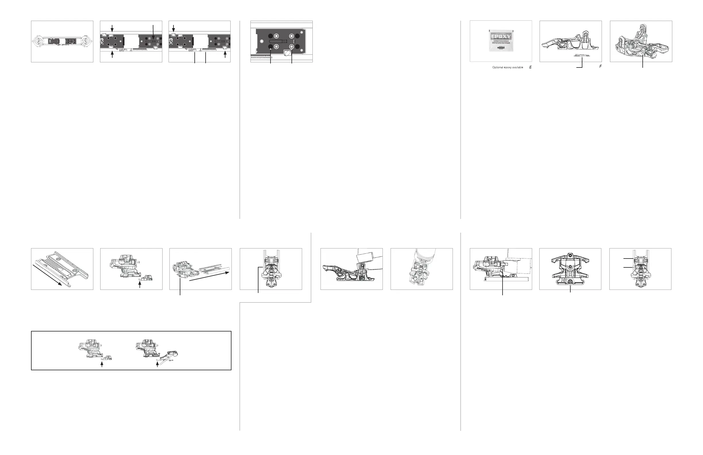
1. SETTING THE BOOT MOUNTING SIZE
Note: this does not align the jig to the ski, instead it sets the boot to the jig.
a. Put the jig on the ski (A). Do not worry about setting the jig in the correct location on the ski. This
step comes later.
b. Click the toe of the ski boot into the jig (B).
c. Adjust the jig plates until the heel of the boot is in contact with the heel stopper (B).
d. Secure by tightening the plate lock screws (C).
e. If the boot is unavailable but the sole length is known, set the jig length by aligning the heel plate
with the BSL scale on the frame of the jig (C).
DEMO / RENTAL VERSIONS
a. Set the jig to one of the rental sizing settings by aligning the bottom of the toe plate with the chosen
size: (C)
Demo-Small (fits ~265-325mm boot sole lengths)
Demo-Medium (fits ~280-340mm boot sole lengths)
Demo-Large (fits ~295-355mm boot sole lengths)
2. DRILL SKIS USING G3 JIG
REGULAR RETAIL VERSIONS
a. Reposition the jig onto the ski and align the center mark of the ski with the center mark of the jig.
For an off center mount (plus 1cm, minus 1cm, etc.) line up the desired mark on the ski with the
center mark of the jig.
b. Rotate the handles to center the jig and secure in place using the spiral lock screws.
c. Select the ski manufacturer’s recommended drill bit size; either 3.5mm or 4.1mm x 9mm
(G3 recommends 4.1mm for skis with metal top sheets). A slight countersink is advised.
d. Drill the toe mounting pattern.
e. Select the retail (non-demo) heel mounting pattern (D) and drill the holes.
e. Ensure all the holes are free of debris.
RENTAL / DEMO VERSIONS
a. Reposition the jig on to the ski and align the center mark of the jig to the center mark of the ski.
b. Rotate the handles to center the jig and secure in place using the spiral lock screws.
c. Select the ski manufacturer’s recommended drill bit size; either 3.5mm or 4.1mm x 9mm
(G3 recommends 4.1mm for skis with metal top sheets). A slight countersink is advised.
d. Drill the toe mounting pattern.
e. Select the demo heel mounting pattern (D) and drill the holes.
f. Ensure all the holes are free of debris.
3. MOUNT TOE ASSEMBLY
a. Completely fill drilled holes with waterproof adhesive.
Note: Using a slow cure epoxy sifnificantly increases the mounting strength and it is
recommended if you are an aggressive or heavy skier, if you commonly carry a loaded pack
or if you use wide skis.
b. Ensure that the toe assembly (2) is in step-in position.
c. Position the toe shim under the toe assembly (F). Refer to the exploded view on the front to
distinuish the toe shim (3) and the toe assembly (2).
d. Install using the mounting screws (1) and a PoziDriv #3 screwdriver.
e. Do not fully tighten screws until after step 5 to first allow for proper alignment of the toe.
f. If the use of a leash (8) is intended, connect the wire loop end of the supplied leash by pushing the
loop through the hole in the control arm tower (G). Then pull the carabiner through the wire loop and
pull to girth hitch.
4. MOUNTING BINDINGS ON TO THE SKI (HEEL)
Note: Do not adjust the length of the binding until the heel screws are fully
tightened down.
YOU MUST USE EITHER SKI BRAKES OR STOMP PAD
a. Install the heel track (5) and plastic heel shim (4) on to the ski using the mounting screws (1) and a
PoziDriv #3 screwdriver. When mounting a rental/demo version use the rental heel track and plastic
heel shim. The track must be mounted with the U shape toward the tip of the ski (H).
b. Install mounting screws (1) and torque to 4 Nm.
c. Connect the stomp pad (6) to the underside of the base of the heel turret (I). The fangs on the rear of the
stomp pad should seat into the pockets on the bottom of the turret.
d. Install the heel turret assembly (7) and stomp pad (6) by driving it on from the back of the heel track
using the length adjustment screw (J) and a PoziDriv #3 screwdriver. Bring the turret forward until the
adjustment limit indicator mark on the turret matches the rear adjustment limit indicator on the heel
track (K).
e. Visually inspect that the heel is mounted tightly to the surface of the ski. There must not be any gap
underneath the heel assembly.
5. ALIGN THE TOE ASSEMBLY
a. Insert the boot toe into the toe of the binding, but do not fully tighten the screws yet (L). Ensure
that the heel turret assembly (7) of the binding is oriented in ski mode.
b. Check the alignment of the heel of the boot with the binding heel (M). If the boot’s heel insert is not
coming down centered between the heel pins, then lock the toe in tour mode, and torque the boot
to the left or right to properly align the boot with the pins.
c. Once the heel of the boot and the pins of the binding are aligned properly, carefully remove the boot
and torque the mounting screws (1) to 4 Nm.
6. SIZE ADJUSTMENT
a. Install the ski boot into the binding with the heel positioned in ski mode.
Note: Ensure the next step occurs without weight on the binding. Ideally this step
is done on the work bench. In a demo situation have the customer unweight their
heel while the ski tech is adjusting the boot sole length.
b. Starting with a gap between the binding and the boot, slowly bring the binding just into contact with
the boot adjusting the length adjustment screw (N). See images above for contact point (N) and
location of length adjustment screw (O).
c. Front, middle, and rear adjustment limit indicator markings can be found on the heel track. The heel
turret assembly (7) should be positioned where the corresponding indicator mark is in between the
rear limit indicator and the front limit indicator markings (P).
WARNING!
It is VERY IMPORTANT not to over tighten the gap. As a check, loosen the length
adjustment screw very slightly. That adjustment should open the gap. Then, remember
to re-adjust the heel of the binding after checking the gap.
Adjustment Limit Indicators
(with binding adjusted to the rear)
Toe shim
G
Control arm tower hole
H I
Length adjustment screw
J
Rear adjustment limit indicator
K N
Contact point
O
Length adjustment screw
P
OK
X
X
Ski tip
L M
OR
A B C
Demo sizing BSL scale Rental/Demo (Black)
D
Retail Holes (White)
 Loading...