EasyManua.ls Logo

GAC EEG6500 - User Manual

GAC EEG6500
8 pages
Print Icon
To Next Page IconTo Next Page
Loading...
1
© 2018 Copyright All Rights Reserved
EEG6500 Enhanced Electronic Governor 05.09.18 PIB 5010 F
EEG6500
Enhanced Electronic Governor
1
2
3
INTRODUCTION
SPECIFICATIONS
INSTALLATION
PERFORMANCE
Isochronous Operation ± 0.25%
Speed Range / Governor
100Hz - 12 KHz
(200-6000 RPM w/120 tooth flywheel) cont.
Idle Adjust Full Range
Droop Range 1 - 25% regulation
Speed Trim Programmable ±120 Hz
INPUT / OUTPUT
Supply 12-24 VDC Battery Systems (7.0 to 32 VDC)
Polarity Negative Ground
Power Consumption 70mA max. continuous plus actuator current
Speed Sensor Signal 1.0-120 VRMS
Actuator Output 8-10 Amps Continuous, Momentary >10A
Max; works with all GAC actuators and ATB’s
except the ADB335 and ACB2001.
Load Share/Synchronizer
Input
0-10 VDC ( 5V nominal, reversed polarity,
145Hz / V )
Reverse Power Protection Ye s
Transient Voltage Protection 60V
Mount in a cabinet, engine
enclosure, or sealed metal box.
Vertical orientation allows for
the draining of fluids in moist
environments.
Avoid Extreme Heat
Internet Connection
Computer
GAC’s EEG6500 digital governor is designed to regulate engine speed on diesel
and gaseous-fueled engines. The EEG system is a suitable replacement for any
mechanical governor system that needs flexibility, precision, or accurate control
of governed speed. The EEG is designed for industrial engine applications from
generator sets, and mechanical drives, to pumps or compressors.
With the use of GAC’s Quikest Display, the EEG requires no computer or Inter-
net connection. It is compatible with all GAC actuators and ATB’s, except the
ADB335 and ACB2001.
With Quikset Display
[mm]
in
Dimensions:
COM VSPD
EEG
Enhanced Electronic Governor
6500
www.governors-america.com
- CAUTION -
ENGINE SPEED CONTROL COMPONENT
SEE PRODUCT PUBLICATION WHEN
INSTALLING OR SERVICING
N P
CAN
M
AUX
IDLE
L
DROOP
KJHG
BATT
FE
H J K L
V.SPD
IDLE
DROOP
A: Actuator
B: Actuator
C: Pickup
D: Pickup
E: Battery -
F: Battery +
G: Not Used
H: Common
J: Variable Speed
K: Droop
L: Idle Select
M: Auxiliary Input
N: CANbus (Low)
P: CANbus (High)
TERMINALS
L H
-
+
PICKUP
DC
ACT
BA
u.s.a.
CBA
Improved & Simplified LCD User Interface
Fast Setup with 5 Push Buttons, No Potentiometers
Rated, Idle Speed, and Variable Speed
Selectable Isochronous, Droop, & Variable Governing
Built-In Fault Protection With Overcurrent Sensing
Adjustable Starting Fuel Strategy (Black Smoke Reduction)
Extended Speed Range to 12KHz or 6000 RPM with Frequency Display
Speed Ramping (Idle to Rated or any Speed Setting)
Includes Standard GAC AUX Input for Synchronizing and Load Sharing
J1939 Engine Data and Speed Output
Overspeed Sensing & Protection
ENVIRONMENTAL
Ambient Temperature -40° to 85°C (-40 to 185°F)
Relative Humidity up to 95%
All Surface Finishes Fungus Proof and Corrosion Resistant
PHYSICAL
Dimension See Section 3 “Installation”
Weight 1.8 lbs. (820 grams)
Mounting Any position, Vertical Preferred
RELIABILITY
Vibration 7G, 20-100 Hz
Shock 20G Peak
Testing 100% Functional Test
COMPLIANCE / STANDARDS
Agency CE, (EN55011, EN50081-2 and EN50082-2)
Communications SAE J1939 (Optional)
An overspeed shutdown device, independent of the governor
system, should be provided to prevent loss of engine control
which may cause personal injury or equipment damage. Do not rely exclusively
on the governor system electric actuator to prevent overspeed. A secondary
shutoff device, such as a fuel solenoid must be used.
WARNING
Question and Answer IconNeed help?

Do you have a question about the GAC EEG6500 and is the answer not in the manual?

Summary

Introduction

EEG6500 Enhanced Electronic Governor

Overview of the EEG6500 digital governor for engine speed regulation.

Specifications

Performance

Technical performance metrics including isochronous operation and speed range.

Environmental

Operating environmental conditions like temperature and humidity.

Input;Output

Electrical inputs and outputs for power, sensors, and actuators.

Physical

Physical dimensions and weight of the governor unit.

Reliability

Reliability data including vibration, shock, and testing standards.

Compliance; Standards

Regulatory compliance and communication standards (CE, J1939).

Installation

Wiring

Recommendations

Important wiring notes and recommendations, including loss of magnetic pickup.

Display & Controls

End User Interface

Features

Trim or Variable Speed Operation

Details on trim and variable speed functions using resistive or voltage input.

Pre-Start Set-Up & Quickset Parameters

Adjustable Quikset Parameters

Parameters to set before starting the engine for optimal performance.

Adjusting for Stability

Gain - Rated Speed & Idle Speed

Procedure for adjusting Gain for stable rated and idle speeds.

Adjusting for Droop

Advanced Parameters Menu

Advanced Menu Parameters (Configurable)

List of advanced parameters that can be configured by the user.

Advanced Menu Parameters (Read Only)

List of advanced parameters that are read-only and for diagnostic use.

OEM Save Settings

OEM Restore

Factory Restore

Fault Codes

J1939 CAN Info

Information regarding J1939 CAN communication and engine speed data.

System Troubleshooting

Unsatisfactory Performance

Overview

The EEG6500 Enhanced Electronic Governor is a digital governor designed to regulate engine speed in diesel and gaseous-fueled engines. It serves as a suitable replacement for mechanical governor systems requiring flexibility, precision, or accurate control of governed speed. The EEG6500 is specifically designed for industrial engine applications, including generator sets, mechanical drives, pumps, and compressors.

Function Description:

The EEG6500's primary function is to maintain precise engine speed. It offers both isochronous operation (maintaining a constant speed regardless of load) and droop governing (allowing speed to decrease slightly with increasing load), as well as variable speed control. The device integrates built-in fault protection with overcurrent sensing to safeguard the system. It also features an adjustable starting fuel strategy to reduce black smoke during startup and an extended speed range up to 12 KHz or 6000 RPM with frequency display. Speed ramping is supported for smooth transitions between idle, rated, or any other speed setting. For advanced applications, it includes a standard GAC AUX input for synchronizing and load sharing, J1939 engine data and speed output, and overspeed sensing and protection.

Important Technical Specifications:

  • Performance:
    • Isochronous Operation: ± 0.25% accuracy.
    • Speed Range / Governor: 100Hz - 12 KHz (200-6000 RPM with a 120-tooth flywheel) continuously.
    • Idle Adjust: Full range.
    • Droop Range: 1 - 25% regulation.
    • Speed Trim: Programmable ±120 Hz.
  • Input/Output:
    • Supply: 12-24 VDC battery systems (7.0 to 32 VDC), negative ground.
    • Power Consumption: 70mA max. continuous plus actuator current.
    • Speed Sensor Signal: 1.0-120 VRMS.
    • Actuator Output: 8-10 Amps continuous, momentary >10A Max. Compatible with all GAC actuators and ATBs except ADB335 and ACB2001.
    • Load Share/Synchronizer Input: 0-10 VDC (5V nominal, reversed polarity, 145Hz/V).
    • Reverse Power Protection: Yes.
    • Transient Voltage Protection: 60V.
  • Environmental:
    • Ambient Temperature: -40° to 85°C (-40 to 185°F).
    • Relative Humidity: Up to 95%.
    • All Surface Finishes: Fungus proof and corrosion resistant.
  • Physical:
    • Weight: 1.8 lbs. (820 grams).
    • Mounting: Any position, vertical preferred for fluid drainage in moist environments.
  • Reliability:
    • Vibration: 7G, 20-100 Hz.
    • Shock: 20G Peak.
    • Testing: 100% functional test.
  • Compliance/Standards:
    • Agency: CE (EN55011, EN50081-2 and EN50082-2).
    • Communications: SAE J1939 (Optional).

Usage Features:

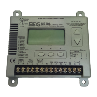
The EEG6500 features an improved and simplified LCD user interface, allowing for fast setup with 5 push buttons and no potentiometers. This eliminates the need for a computer or internet connection when used with GAC's Quikset Display. Users can select between rated, idle, and variable speed settings, and choose between isochronous, droop, and variable governing modes. The system also supports speed ramping from idle to rated or any other speed setting.

The Quikset Menu provides access to various adjustable parameters such as OVER SPEED, #TEETH (number of teeth on the flywheel), CRANK (crank termination RPM), SPEED (fixed or droop operating speed), SPEED RAMP, V.SPEED (variable speed or trim), START FUEL (initial actuator position at cranking), DROOP%, LOCKED (manual/auto locking of display), FUEL RAMP, GAIN (proportional set point of PID control), IDLE (engine speed when idle input is closed), STABILITY (integral set point of PID control), FUEL LIM (maximum actuator percentage allowed), and DEADTIME (derivative set point of PID control).

The device includes a "Lock Feature" to prevent unauthorized changes to parameters. It also offers "OEM Save Settings" to copy current settings to a separate configuration area for later restoration, and "OEM Restore" to load these saved settings.

Maintenance Features:

The manual provides comprehensive troubleshooting guides for system inoperative conditions, instability (fast periodic, slow periodic, non-periodic), engine overspeeds, and situations where the actuator does not energize fully or the engine remains below desired governed speed. It includes electrical checks for battery supply voltage, speed sensor signal, and actuator output, along with probable causes and customer actions for various fault codes.

The EEG6500 also logs fault codes, including actuator overcurrent, loss of speed signal, overspeed, variable speed settings reversed, no potentiometer/signal detected, new/incompatible software loaded, and FLCU/NLCU setting invalid. These codes aid in diagnosing and resolving issues. The device's design, with vertical mounting preferred, facilitates the draining of fluids in moist environments, contributing to its longevity. Regular checks of actuator wiring, speed pickup, fuel system, and potentiometer wiring are recommended for maintenance.

GAC EEG6500 Specifications

General IconGeneral
BrandGAC
ModelEEG6500
CategoryController
LanguageEnglish