Coupling Alignment Gage Operation Manual
Copyright © 2016 Gagemaker. All rights reserved
6
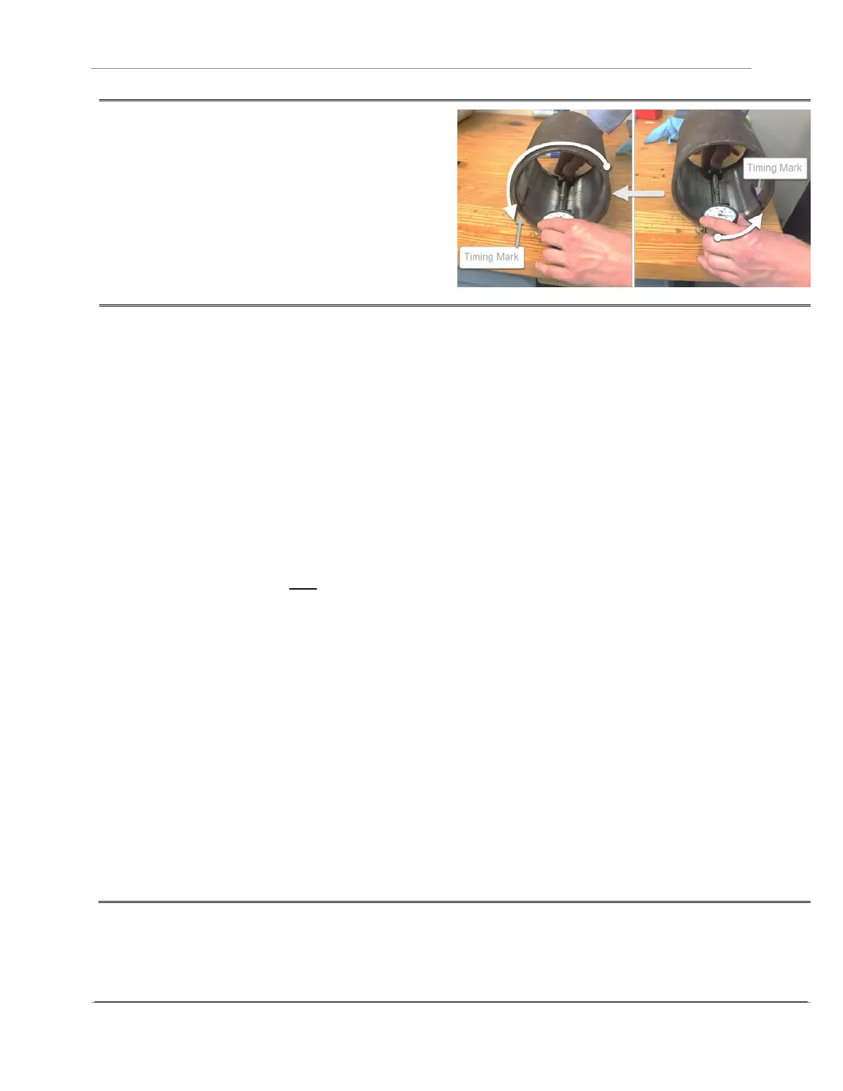
9. Roll the coupling one complete revolution and
make note of the minimum and maximum
indications.
TIP: Roll the coupling by keeping both hands on
the gage and pushing the gage down and
forward.
10. Determine the total sweep by subtracting the
minimum indication from the maximum
indication.
The total sweep of the coupling must not
exceed the maximum sweep value recorded
in the tables found in the Maximum Sweep
Value tables on page 7 & 8.
The maximum sweep values were calculated
using the following equation from API
Specification 5B Section 5.1.35.
where
R = maximum permissible sweep of the
dial gauge indicator;
E = pitch diameter of the coupling where
the contact points on the gauge are
located. This must be calculated for the
coupling being inspected;
A = maximum allowable misalignment in
20 ft. API Specification 5B Section 4.1.10
states that the maximum angular
misalignment shall not exceed ¾” per 20’
of the projected axis for all tubing and
casing sizes.