CONTENTS
1 INTRODUCTION1 INTRODUCTION
1 INTRODUCTION1 INTRODUCTION
1 INTRODUCTION
2 OPERA2 OPERA
2 OPERA2 OPERA
2 OPERA
TOR CONTROLSTOR CONTROLS
TOR CONTROLSTOR CONTROLS
TOR CONTROLS
3 TECHNICAL INFORMA3 TECHNICAL INFORMA
3 TECHNICAL INFORMA3 TECHNICAL INFORMA
3 TECHNICAL INFORMA
TIONTION
TIONTION
TION
5 COMMISSIONING5 COMMISSIONING
5 COMMISSIONING5 COMMISSIONING
5 COMMISSIONING
7 F7 F
7 F7 F
7 F
AULAUL
AULAUL
AUL
T FINDINGT FINDING
T FINDINGT FINDING
T FINDING
CONTENTSCONTENTS
CONTENTSCONTENTS
CONTENTS
ImporImpor
ImporImpor
Impor
tant Informationtant Information
tant Informationtant Information
tant Information
----------------------------------------------------------------------------------
----------------------------------------------------------------------------------
----------------------------------------- 4
Section 1 IntrSection 1 Intr
Section 1 IntrSection 1 Intr
Section 1 Intr
oductionoduction
oductionoduction
oduction
1-1 Introduction ---------------------------------------------- 5
1-2 System Layout ------------------------------------------- 8
1-3 Parts Supplied------------------------------------------- 11
1-4 The Electrastream System ------------------------------- 12
1-5 Tri Core Heater Operation -------------------------------- 13
Section 2 Operator ContrSection 2 Operator Contr
Section 2 Operator ContrSection 2 Operator Contr
Section 2 Operator Contr
olsols
olsols
ols
2-1 System Control ------------------------------------------ 14
2-2 Electrastream Control Unit ------------------------------- 16
2-3 Shut Off Valves ------------------------------------------ 20
2-4 Temperature & Pressure Relief Discharge---------------- 22
2-5 Thermostatic Mixing Valve ------------------------------ 22
2-6 Servicing ------------------------------------------------ 22
Section 3 TSection 3 T
Section 3 TSection 3 T
Section 3 T
echnical Informationechnical Information
echnical Informationechnical Information
echnical Information
3-1 Specifications ------------------------------------------- 23
3-2 Dimensions --------------------------------------------- 25
3-3 Wiring --------------------------------------------------- 29
Section 4 InstallationSection 4 Installation
Section 4 InstallationSection 4 Installation
Section 4 Installation
4-1 Building Control ----------------------------------------- 31
4-2 Electrical ------------------------------------------------ 31
4-3 Hot Water System --------------------------------------- 33
4-4 Heating System ----------------------------------------- 37
4-5 Expansion Discharge ------------------------------------ 40
4-6 System Pressure ---------------------------------------- 43
4-7 Electrastream Connections - ---------------------------- 44
Section 5 CommissioningSection 5 Commissioning
Section 5 CommissioningSection 5 Commissioning
Section 5 Commissioning
5-1 Commissioning ----------------------------------------- 47
Section 6 ServicingSection 6 Servicing
Section 6 ServicingSection 6 Servicing
Section 6 Servicing
6-1 Routine Service ----------------------------------------- 50
Section 7 Fault FindingSection 7 Fault Finding
Section 7 Fault FindingSection 7 Fault Finding
Section 7 Fault Finding
7-1 Fault Finding -------------------------------------------- 52
Health & SafetyHealth & Safety
Health & SafetyHealth & Safety
Health & Safety
------------------------------------------------------------
------------------------------------------------------------
------------------------------ Inside Front Cover
6 SERVICING6 SERVICING
6 SERVICING6 SERVICING
6 SERVICING
4 INST4 INST
4 INST4 INST
4 INST
ALLAALLA
ALLAALLA
ALLA
TIONTION
TIONTION
TION
IMPORTANT
BEFORE STARTING THE INSTALLATION OF THE ELECTRASTREAM CHECK ALL COMPONENTS HAVE
BEEN DELIVERED AND ARE IN SATISFACTORY CONDITION - Refer to 1-3 .
HEALHEAL
HEALHEAL
HEAL
TH & SAFETYTH & SAFETY
TH & SAFETYTH & SAFETY
TH & SAFETY
21
2-3.1 Stop Cock
Normally located at the point where the mains supply enters the dwelling.
Shuts off the mains water supply to the dwelling.
2-3.2 Double Check Valve (If fitted)
Normally located after the Stop Cock. Prevents water back-feeding to main.
Shuts off the mains water supply to the dwelling.
2-3.3 Cold Water Shut Off Valve
Located in the cold feed to the taps/outlets.
Shuts off the cold water to the taps/outlets.
2-3.4 Supply Water Shut Off Valve
Normally located where the cold supply connects to the combination valve on the
cylinder.
Shuts off the cold supply to the Electrastream system.
2-3.5 Hot Water Shut Off Valve
Normally located where the Domestic Hot Water feed comes from the cylinder.
Shuts off the hot water to the taps.
2-3.6 Accumulator Isolating Valve
ELECTRASTREAM PLUS ONLY
Located in the feed from the accumulator. Isolates water in accumulator.
Note
When opening the stop cock turn the valve
fully open then close ½ turn, this prevents
the valve sticking.
OPERAOPERA
OPERAOPERA
OPERA
TOR CONTROLS 2TOR CONTROLS 2
TOR CONTROLS 2TOR CONTROLS 2
TOR CONTROLS 2
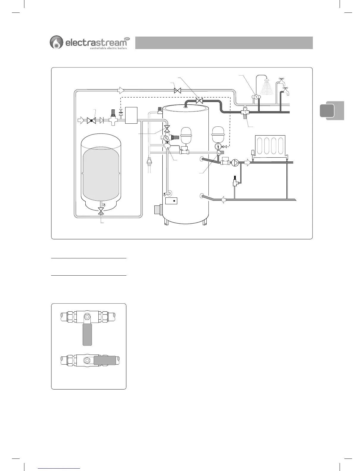
Fig. 2-3b Typical Shut Off Valve Locations - Electrastream Plus
Fig. 2-3c Valves
OPEN
CLOSED
22
22
2
 Loading...