CONTENTS
1 INTRODUCTION1 INTRODUCTION
1 INTRODUCTION1 INTRODUCTION
1 INTRODUCTION
2 OPERA2 OPERA
2 OPERA2 OPERA
2 OPERA
TOR CONTROLSTOR CONTROLS
TOR CONTROLSTOR CONTROLS
TOR CONTROLS
3 TECHNICAL INFORMA3 TECHNICAL INFORMA
3 TECHNICAL INFORMA3 TECHNICAL INFORMA
3 TECHNICAL INFORMA
TIONTION
TIONTION
TION
5 COMMISSIONING5 COMMISSIONING
5 COMMISSIONING5 COMMISSIONING
5 COMMISSIONING
7 F7 F
7 F7 F
7 F
AULAUL
AULAUL
AUL
T FINDINGT FINDING
T FINDINGT FINDING
T FINDING
CONTENTSCONTENTS
CONTENTSCONTENTS
CONTENTS
ImporImpor
ImporImpor
Impor
tant Informationtant Information
tant Informationtant Information
tant Information
----------------------------------------------------------------------------------
----------------------------------------------------------------------------------
----------------------------------------- 4
Section 1 IntrSection 1 Intr
Section 1 IntrSection 1 Intr
Section 1 Intr
oductionoduction
oductionoduction
oduction
1-1 Introduction ---------------------------------------------- 5
1-2 System Layout ------------------------------------------- 8
1-3 Parts Supplied------------------------------------------- 11
1-4 The Electrastream System ------------------------------- 12
1-5 Tri Core Heater Operation -------------------------------- 13
Section 2 Operator ContrSection 2 Operator Contr
Section 2 Operator ContrSection 2 Operator Contr
Section 2 Operator Contr
olsols
olsols
ols
2-1 System Control ------------------------------------------ 14
2-2 Electrastream Control Unit ------------------------------- 16
2-3 Shut Off Valves ------------------------------------------ 20
2-4 Temperature & Pressure Relief Discharge---------------- 22
2-5 Thermostatic Mixing Valve ------------------------------ 22
2-6 Servicing ------------------------------------------------ 22
Section 3 TSection 3 T
Section 3 TSection 3 T
Section 3 T
echnical Informationechnical Information
echnical Informationechnical Information
echnical Information
3-1 Specifications ------------------------------------------- 23
3-2 Dimensions --------------------------------------------- 25
3-3 Wiring --------------------------------------------------- 29
Section 4 InstallationSection 4 Installation
Section 4 InstallationSection 4 Installation
Section 4 Installation
4-1 Building Control ----------------------------------------- 31
4-2 Electrical ------------------------------------------------ 31
4-3 Hot Water System --------------------------------------- 33
4-4 Heating System ----------------------------------------- 37
4-5 Expansion Discharge ------------------------------------ 40
4-6 System Pressure ---------------------------------------- 43
4-7 Electrastream Connections - ---------------------------- 44
Section 5 CommissioningSection 5 Commissioning
Section 5 CommissioningSection 5 Commissioning
Section 5 Commissioning
5-1 Commissioning ----------------------------------------- 47
Section 6 ServicingSection 6 Servicing
Section 6 ServicingSection 6 Servicing
Section 6 Servicing
6-1 Routine Service ----------------------------------------- 50
Section 7 Fault FindingSection 7 Fault Finding
Section 7 Fault FindingSection 7 Fault Finding
Section 7 Fault Finding
7-1 Fault Finding -------------------------------------------- 52
Health & SafetyHealth & Safety
Health & SafetyHealth & Safety
Health & Safety
------------------------------------------------------------
------------------------------------------------------------
------------------------------ Inside Front Cover
6 SERVICING6 SERVICING
6 SERVICING6 SERVICING
6 SERVICING
4 INST4 INST
4 INST4 INST
4 INST
ALLAALLA
ALLAALLA
ALLA
TIONTION
TIONTION
TION
IMPORTANT
BEFORE STARTING THE INSTALLATION OF THE ELECTRASTREAM CHECK ALL COMPONENTS HAVE
BEEN DELIVERED AND ARE IN SATISFACTORY CONDITION - Refer to 1-3 .
HEALHEAL
HEALHEAL
HEAL
TH & SAFETYTH & SAFETY
TH & SAFETYTH & SAFETY
TH & SAFETY
41
INSTINST
INSTINST
INST
ALLAALLA
ALLAALLA
ALLA
TION 4TION 4
TION 4TION 4
TION 4
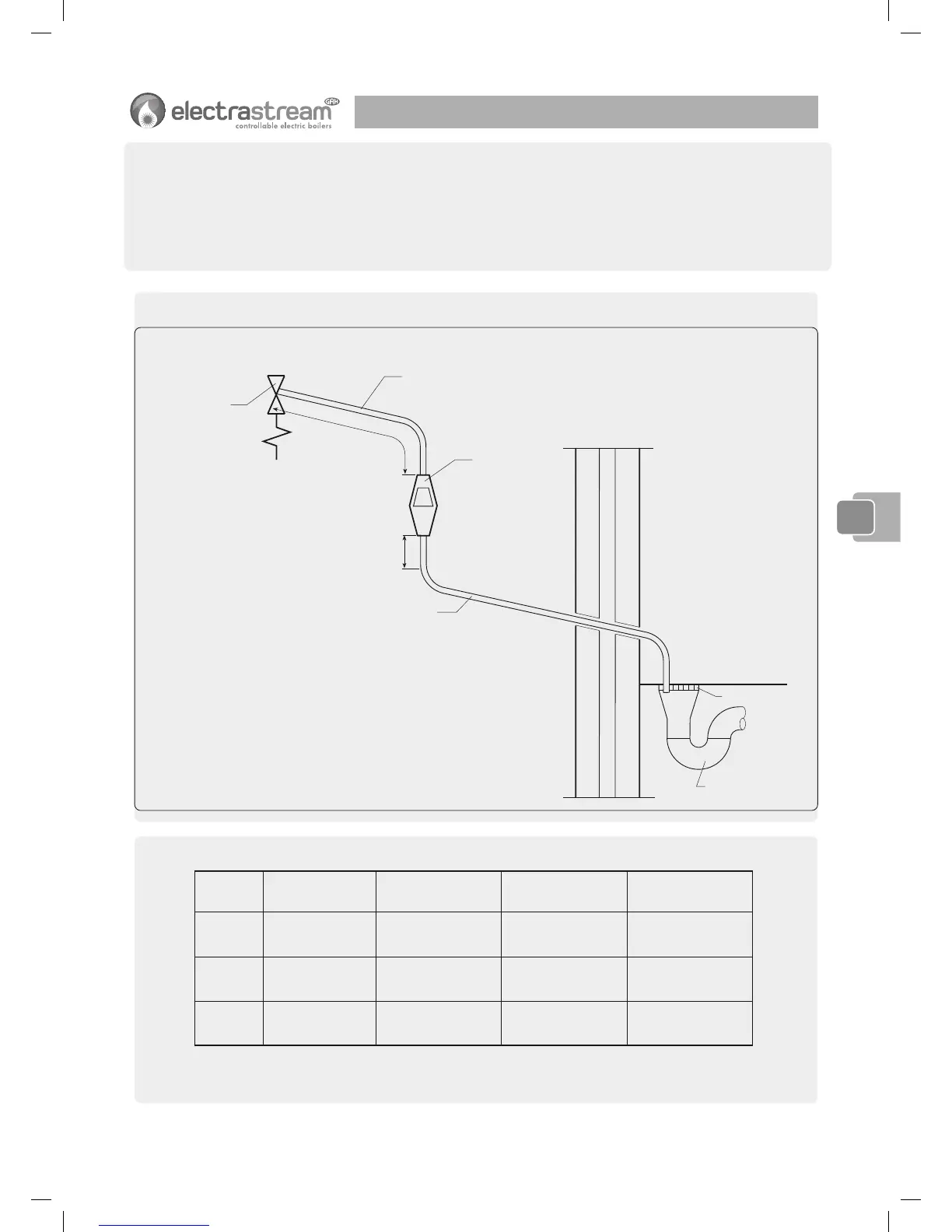
Diagram 1
TT
TT
T
ypical discharypical dischar
ypical discharypical dischar
ypical dischar
ge pipe arrangementge pipe arrangement
ge pipe arrangementge pipe arrangement
ge pipe arrangement
ezistel tuoevlaV
egrahcsidfoezismuminiM
( h s i d n u To t1D1D
1D
1D1D*)
epipegrahcsidfoezismuminiM
( h s i d n u Tm o r f2D2D
2D
2D2D*)
d e w o l l ae c n a t s i s e rm u m i x a M
thgiar tsfohtgnelasadesserpxe
sdnebr oswob l eon. e . i , ep i p
hcaeybde t ae r cecna t s i seR
d n e b r ow o b l e
½Gmm5 1
mm2 2
mm8 2
mm5 3
m9 o t p u
m8 1 o t p u
m7 2 o t p u
m8 . 0
m0 . 1
m4 . 1
¾Gmm2 2
mm8 2
mm5 3
mm2 4
m9 o t p u
m8 1 o t p u
m7 2 o t p u
m0 . 1
m4 . 1
m7 . 1
1Gmm8 2
mm5 3
mm2 4
mm4 5
m9 o t p u
m8 1 o t p u
m7 2 o t p u
m4 . 1
m7 . 1
m3 . 2
Table 1
Sizing of copper discharSizing of copper dischar
Sizing of copper discharSizing of copper dischar
Sizing of copper dischar
ge pipe D2 for common temperaturge pipe D2 for common temperatur
ge pipe D2 for common temperaturge pipe D2 for common temperatur
ge pipe D2 for common temperatur
e re r
e re r
e r
elief valve outlet sizeselief valve outlet sizes
elief valve outlet sizeselief valve outlet sizes
elief valve outlet sizes
*See 3.49 and 3.56 and Diagram 1
Note: The above table is based on copper tube. Plastic pipes may be of different bore and resistance.
Sizes and maximum lengths of plastic should be calculated using data prepared for the type of pipe being used.
pipe 9m long, i.e. for discharge pipes between 9m and 18m the
equivalent resistance length should be at least two sizes larger
than the nominal outlet size of the safety device; between 18
and 27m at least 3 sizes larger, and so on; bends must be taken
into account in calculating the flow resistance. See Diagram 1,
Table 1 and the worked example.
Note: Note:
Note: Note:
Note: An alternative approach for sizing discharge pipes would
be to follow Annex D, section D.2 of BS 6700:2006
Specification for design, installation, testing and maintenance of
services supplying water for domestic use within buildings and
their curtilages.
44
44
4
 Loading...