CONTENTS
1 INTRODUCTION1 INTRODUCTION
1 INTRODUCTION1 INTRODUCTION
1 INTRODUCTION
2 OPERA2 OPERA
2 OPERA2 OPERA
2 OPERA
TOR CONTROLSTOR CONTROLS
TOR CONTROLSTOR CONTROLS
TOR CONTROLS
3 TECHNICAL INFORMA3 TECHNICAL INFORMA
3 TECHNICAL INFORMA3 TECHNICAL INFORMA
3 TECHNICAL INFORMA
TIONTION
TIONTION
TION
5 COMMISSIONING5 COMMISSIONING
5 COMMISSIONING5 COMMISSIONING
5 COMMISSIONING
7 F7 F
7 F7 F
7 F
AULAUL
AULAUL
AUL
T FINDINGT FINDING
T FINDINGT FINDING
T FINDING
CONTENTSCONTENTS
CONTENTSCONTENTS
CONTENTS
ImporImpor
ImporImpor
Impor
tant Informationtant Information
tant Informationtant Information
tant Information
----------------------------------------------------------------------------------
----------------------------------------------------------------------------------
----------------------------------------- 4
Section 1 IntrSection 1 Intr
Section 1 IntrSection 1 Intr
Section 1 Intr
oductionoduction
oductionoduction
oduction
1-1 Introduction ---------------------------------------------- 5
1-2 System Layout ------------------------------------------- 8
1-3 Parts Supplied------------------------------------------- 11
1-4 The Electrastream System ------------------------------- 12
1-5 Tri Core Heater Operation -------------------------------- 13
Section 2 Operator ContrSection 2 Operator Contr
Section 2 Operator ContrSection 2 Operator Contr
Section 2 Operator Contr
olsols
olsols
ols
2-1 System Control ------------------------------------------ 14
2-2 Electrastream Control Unit ------------------------------- 16
2-3 Shut Off Valves ------------------------------------------ 20
2-4 Temperature & Pressure Relief Discharge ---------------- 22
2-5 Thermostatic Mixing Valve ------------------------------ 22
2-6 Servicing ------------------------------------------------ 22
Section 3 TSection 3 T
Section 3 TSection 3 T
Section 3 T
echnical Informationechnical Information
echnical Informationechnical Information
echnical Information
3-1 Specifications ------------------------------------------- 23
3-2 Dimensions --------------------------------------------- 25
3-3 Wiring --------------------------------------------------- 29
Section 4 InstallationSection 4 Installation
Section 4 InstallationSection 4 Installation
Section 4 Installation
4-1 Building Control ----------------------------------------- 31
4-2 Electrical ------------------------------------------------ 31
4-3 Hot Water System --------------------------------------- 33
4-4 Heating System ----------------------------------------- 37
4-5 Expansion Discharge ------------------------------------ 40
4-6 System Pressure ---------------------------------------- 43
4-7 Electrastream Connections - ---------------------------- 44
Section 5 CommissioningSection 5 Commissioning
Section 5 CommissioningSection 5 Commissioning
Section 5 Commissioning
5-1 Commissioning ----------------------------------------- 47
Section 6 ServicingSection 6 Servicing
Section 6 ServicingSection 6 Servicing
Section 6 Servicing
6-1 Routine Service ----------------------------------------- 50
Section 7 Fault FindingSection 7 Fault Finding
Section 7 Fault FindingSection 7 Fault Finding
Section 7 Fault Finding
7-1 Fault Finding -------------------------------------------- 52
Health & SafetyHealth & Safety
Health & SafetyHealth & Safety
Health & Safety
------------------------------------------------------------
------------------------------------------------------------
------------------------------ Inside Front Cover
6 SERVICING6 SERVICING
6 SERVICING6 SERVICING
6 SERVICING
4 INST4 INST
4 INST4 INST
4 INST
ALLAALLA
ALLAALLA
ALLA
TIONTION
TIONTION
TION
IMPORTANT
BEFORE STARTING THE INSTALLATION OF THE ELECTRASTREAM CHECK ALL COMPONENTS HAVE
BEEN DELIVERED AND ARE IN SATISFACTORY CONDITION - Refer to 1-3 .
HEALHEAL
HEALHEAL
HEAL
TH & SAFETYTH & SAFETY
TH & SAFETYTH & SAFETY
TH & SAFETY
49
STAGE 9 - ACCUMULATOR PRESSURE
Accumulators are supplied by GAH with a preset air charge of 2 Bar (28/30psi). The
Combination Valve supplied with the Electrastream Plus has an integral pressure
reducing valve fixed at 3.5 Bar. Therefore there is a pressure differential of 1.5 bar
between the system pressure and the air charge of the Accumulator.
When the incoming mains pressure is less than 3.5 Bar the pressure differential will be
less than 1.5 Bar and the Accumulator will not fill sufficiently, therefore it may be
necessary to lower the Accumulator air charge pressure.
The procedure for changing the Accumulator pressure is given below, this can be done
before the system has been filled. It may be done after the system has been filled and
tested, providing the incoming main has been turned OFF and the water drained from the
Accumulator. Failure to do this may result in false pressure reading and damage to the
butyl diaphragm.
If mains pressure is 3.5 Bar or above, changing the Accumulator charge pressure will not
be necessary.
Adjusting Air Pressure
9-1 Record mains pressure.
9-2 Turn main supply OFF.
9-3 Turn on cold outlets to empty Accumulator.
9-4 Remove black cap from top of Accumulator check/confirm Accumulator pressure
with pressure gauge.
9-5 Lower air charge so that is 1 to 1.5 Bar below mains pressure.
Minimum Accumulator pressure is 0.8 Bar.
STAGE 10 - HANDING OVER
10.1 Complete the Guarantee Form, the top sheet of this MUST be sent to GAH (HEATING
PRODUCTS) LIMITED or the Electrastream can be registered on-line at
www.gah.co.uk.
10.2 Complete the Benchmark Logbook.
10.3 The Installer should re-check the system and ensure it is completely satisfactory
before demonstrating to the end user.
10.4 The end user should be aware of the following:-
1. The most cost effective use of the Electrastream system using economy and
standard tariffs.
2. How to set the temperature of the tap hot water (Mixing Valve).
3. How to set all Electrastream Controller functions.
4. How to set room thermostat.
5. The function of the Pressure Relief Valves and Combination Valve and that over
pressure will cause steam and scalding water to be emitted from the discharge
pipes.
6. That the Tundish is supplied as a visual identification for over pressure.
7. The procedure to follow in the event of over pressure. Refer to Fault Finding
(section 7).
10.5 This manual and supplements must be left with the end user together with a copy of
the completed Guarantee Form.
COMMISSIONING 5COMMISSIONING 5
COMMISSIONING 5COMMISSIONING 5
COMMISSIONING 5
CAUTION
The main supply must be turned
OFF and water drained from the
Accumulator before lowering the
charge pressure, failure to do so
could result in damage to the
diaphragm.
If in doubt consult GAH (Heating
Products).
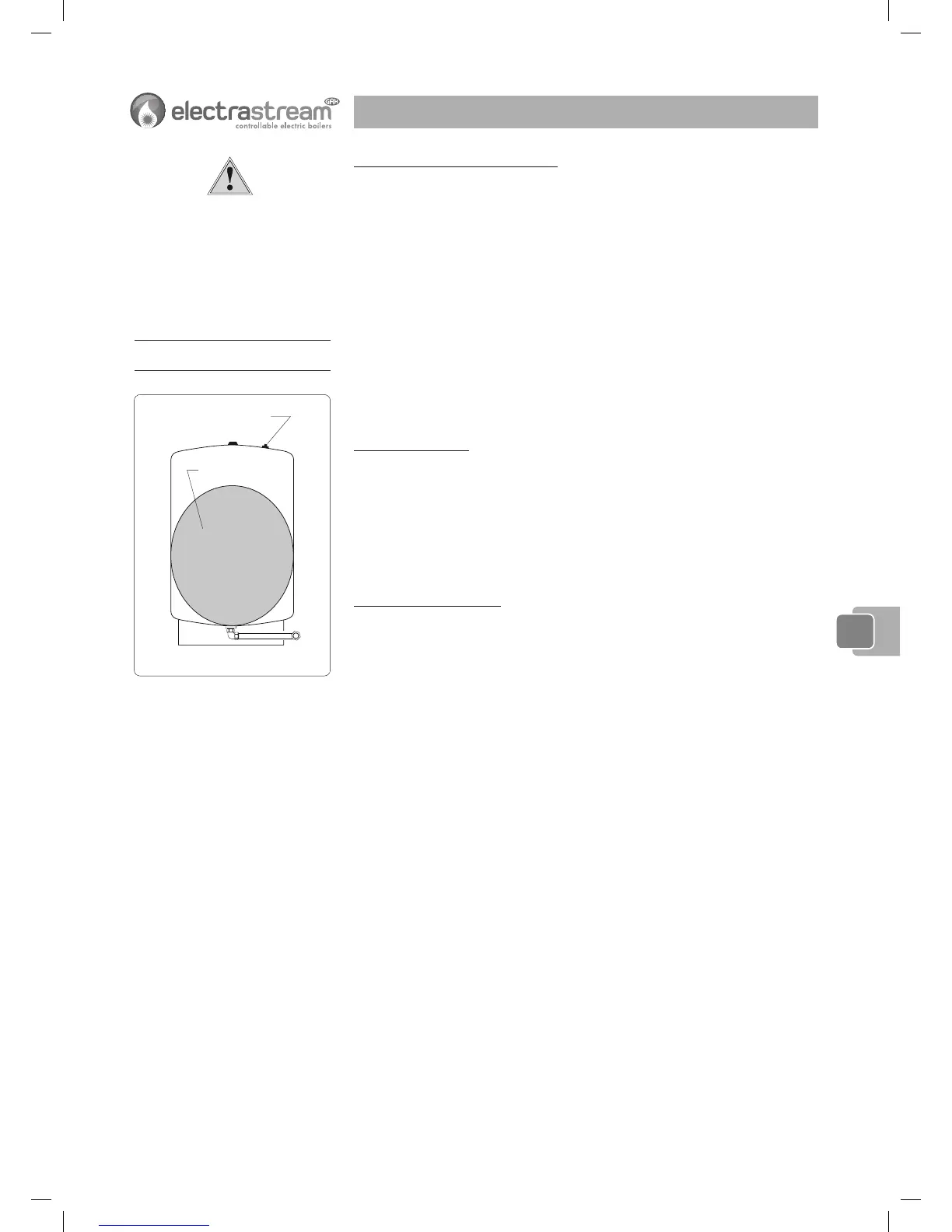
Fig. 5-1a Accumulator Pressure
55
55
5
 Loading...