TABLE OF CONTENTS
Page
. . . . . . . . . . . . . . . . . . . . . . . . . . . . . . . . . . . .
2
Installation
Location . . . . . . . . . . . . . . . . . . . . . . . . . . . . . . . . . . . . .
4
Mounting the Radio . . . . . . . . . . . . . . . . . . . . . . . 4
Ignition Noise Interference . . . . . . . . . . . . . . . . . . . . . . 5
Antenna . . . . . . . . . . . . . . . . . . . . . . . . . . . . . . . . . . . . 5
Tuning the Antenna for Optimum SWR . . . . . . . . . . . . 6
External Speaker . . . . . . . . . . . . . . . . . . . . . . . . . . . . . . 6
Control Functions . . . . . . . . . . . . . . . . . . . . . . . . . . . . . 7
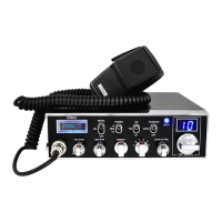
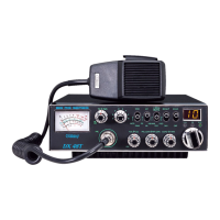
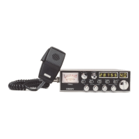
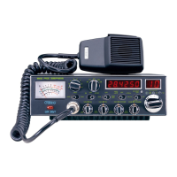
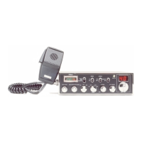
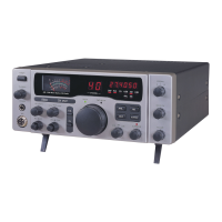
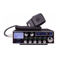
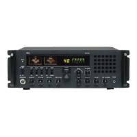
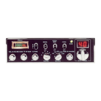
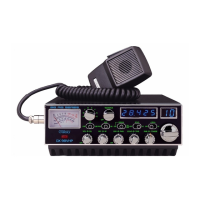
A. Front Panel . . . . . . . . . . . . . . . . . . . . . . . . . . . . . . . . 7
B. Rear Panel . . . . . . . . . . . . . . . . . . . . . . . . . . . . . . . . . 9
Press-To-Talk Microphone . . . . . . . . . . . . . . . . . . . . . . 10
Operating Procedure to Receive . . . . . . . . . . . . . . . . . . 10
Operating Procedure to Transmit . . . . . . . . . . . . . . . . . 10
Alternate Microphones and Installation . . . . . . . . . . . . 11
Warranty . . . . . . . . . . . . . . . . . . . . . . . . . . . . . . . . . .. .
14
Specifications
Frequency Range 28.145 to 28.575 MHz
Frequency Control Phase Lock Loop (PLL) synthesizer.
Frequency Tolerance 0.005%
Frequency Stability 0.001%
Operating Temperature
Range
-30 °C to +50 °C.
Microphone Plug-in dynamic; with push-to-talk switch and
coiled cord.
Input Voltage
Current
13.8V DC nominal, 15.9V max, 11.7V min.
(Positive or negative ground).
Transmit: AM/FM Hi Power _ 10A.
Receiver: Squelched, _ 0.3A.
Maximum Audio output, _ 0.7A.
Size 2-3/8” (H) x 7-7/8” (W) x 9-1/4” (D).
Weight 5.0 1bs.
Antenna Connector UHF, SO239
Meter Illuminated; indicates relative output power,
received signal strength.
TRANSMITTER
Power output AM/FM,-Selectable
LO 0.5W/MED 3W/HI 10W
Modulation High-and low-level Class B, Amplitude
Modulation: AM. Variable capacitance
Frequency Modulation: FM.
Spurious Emissions 60 dB
Frequency Response AM and FM: 300 to 2500 Hz.
Output Impedance 50 ohms, unbalanced
Output Indicators Meter- shows relative RF output power.
Transmit LED glows red when transmitter is
in operation.
- 2 -
- 1 -