L
Lauren PattersonAug 5, 2025
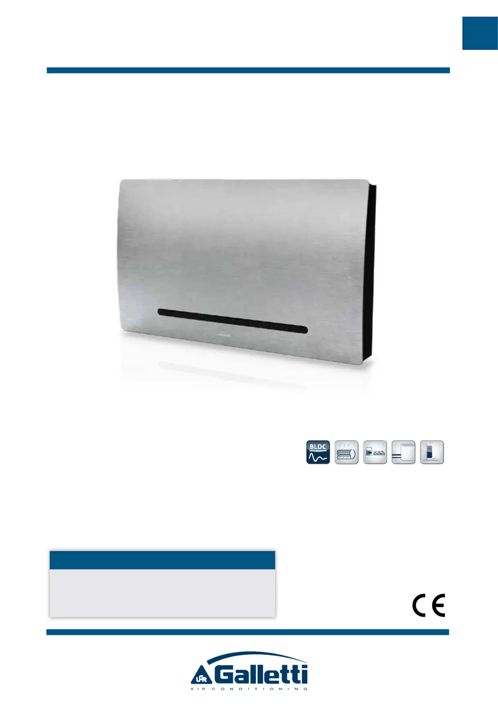
What to do if my Galletti ART-U 10 Air Conditioner fails to work?
- MMike AndersonAug 5, 2025
If your Galletti Air Conditioner isn't working, the first thing to check is the power supply—ensure it's properly connected and restored. If the automatic safety cutout has tripped, it's best to call a service center for assistance. Also, make sure the on/off switch is correctly set to 'I' to start the unit.