Do you have a question about the Galletti Mycomfort Medium and is the answer not in the manual?
Describes the ERGO solution for connecting controllers.
Describes the SMALL solution for Master-Slave systems.
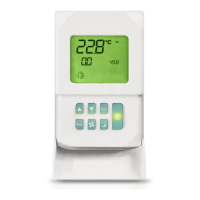
Explains the symbols and indicators on the LCD panel.
Function of the On/Off button for thermostat control.
Function of Up and Down buttons for temperature adjustment.
Function of the SEL button for heating element selection.
Function of the Mode button for selecting operating mode.
Function of the Fan button for selecting fan speed.
Function of the EC button for selecting Economy mode.
Parameter for selecting the type of unit to be governed.
Parameter for specifying the controller installation method.
Parameter for setting the Modbus network address.
Parameter for auto cooling/heating changeover based on air temp.
Parameter to indicate the presence of a water sensor.
Parameter for configuring digital input logic.
Parameter for digital input 1 logic configuration.
Parameter for digital input 2 logic configuration.
Parameter to indicate the presence of a remote humidity sensor.
Details for configuration 001.
Details for configuration 002.
Details for configuration 003.
Details for configuration 004.
Details for configuration 005.
Details for configuration 006.
Details for configuration 007.
Details for configuration 008.
Details for configuration 009.
Details for configuration 010.
Details for configuration 011.
Details for configuration 012.
Details for configuration 013.
Details for configuration 014.
Details for configuration 031.
Details for configuration 032.
Details for configuration 033.
Details for configuration 034.
Details for configuration 035.
Details for configuration 036.
Details for configuration 037.
Details for configuration 038.
Details on connecting to the RS485 communication network.
General structure of the RS485 communication network.
Communication setup for the ERGO solution.
Communication setup for the SMALL solution.
Visual guide for setting up the communication network.
Explains the different logics for selecting thermostat operating modes.
Discusses fan operation and speed selection.
How to select fan speed using the Fan key.
Fan speed selection based on temperature and room air.
Ventilation operation based on system water temperature control.
Overrides normal fan logic for specific situations.
Controls 2 or 3-way ON/OFF type valves.
Control of valve opening based on setpoint and air temperature.
Water temperature check for valve opening.
Provides support in heating mode.
How to select the heating element via the Sel key.
How the heating element is activated.
Water temperature logic for heating element activation.
Information displayed regarding the heating element.
How to activate the Economy function.
Indication of Economy mode on the display.
How to select or deselect the dehumidification function.
Explains the logic and target humidity for dehumidification.
How to select minimum temperature control.
How minimum temperature control activates the unit.
Water control logic for dehumidification function.
Information displayed for dehumidification status.
Alarms that cause forced shutdown of the thermostat.
Alarms that disable critical functions but not shutdown.
List of implemented Modbus functions.
List of implemented Modbus exceptions.
Table of parameters monitored via Modbus.
Description of registers that can only be read.
Description of the Status register.
Description of the AIR TEMPERATURE register.
Description of the HUMIDITY register.
Description of the WATER TEMPERATURE register.
Description of the P00 parameter register.
Description of the T. ACTIVE SETPOINT register.
Description of the T. USER SETPOINT register.
Description of the LCD VERSION register.
Description of registers that can be read and written.
Description of the Digital 1 register bits.
Table mapping units to their corresponding diagrams.
Explanation of symbols used in wiring diagrams.
Step-by-step guide for mounting the controller on a wall.
| Communication | Modbus RTU |
|---|---|
| Operating Temperature | 0°C to +50°C |
| Storage Temperature | -20°C to +60°C |
| Relative Humidity | 5% to 95% (non-condensing) |
| Weight | 0.15 kg |
| Compatibility | Galletti fan coil units |