2
SAFETY PRECAUTIONS
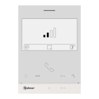
- Hands-free monitor (“ART 4TH LITE” monitor allow handset communication, too).
- 4,3 olo r ." TFT c u screen
.
- for access and selection of menu function .Function push buttons (see page 3)
- Monitor .with simple installation (non-polarised 2 wires bus)
- .Settings menu (settings see page 3)
.
- .Installer menusettings
.
- 50mA/12V ).Output auxiliary call repeater (max. dc
.
- "HZ" input for calls from apartment front door.
.
- Push buttons for door release 1 and 2.
.
- Push-button LED blinks indicating "channel busy".
.
- call (1 to 128) end of line.Configuration switches to assign the address and
- before installing or making modifications to the device.Always disconnect the power supply
.
- The fitting and handling of these devices must be carried out by .authorised personnel
.
- The wiring must run at least 40 cm. away from any other wiring.
- Do not overtighten the screws on the connector.
- Install the monitor in a dry protected location free from the risk of dripping or splashing water.
- Do not place in humid, dusty or smoky locations, or near sources of heat.
- Before connecting the device to the mains, check the connections between the door panel, power
supply, distributors and monitors.
- Always follow the instructions contained in this manual.
CHARACTERISTICS
SYSTEM OPERATION
*
( )
*
( )
3
DESCRIP MONITORTION
*
( )
*
( )
*
( )
INSTAL A MONITORL TION OF THE
*
( )
Building / Villa (Nexa Door Panel)
*
( )
ENEN
- To make a call, the visitor must press the button of the apartment; an audible sound indicates that the call is
being made and LED will turn on. If vocal synthesis is enabled, a 'Call is in progress'door panel
message appears indicating that a call is being made. At this moment, the apartment's monitors receive
the call. If another apartment is called by mistake, press the button for the correct apartment and the first
call will be cancelled.
- Upon receiving the call, the image will appear on the screen of the master monitor (and slave 1, if it exists)
without the visitor knowing To view the image from slave monitors 2 or 3, press. one of the buttons of the
monitor to display the image and the button will blink white. If the call is not answered within 45
seconds, LED will turn off and the system will become free.door panel
- To establish communication, press , door panel LED will turn off and the led willthe button on monitor
turn on.
- Co will last for 90 seconds or untilmmunication the button monitor is .on pressed When communication
ends, LED will turn off and the system will become free. If vocal synthesis is enabled, adoor panel
'Communication is finished' message willindicatethatthe call is over.
- If you wish to open the door, press the push-button (if it exists and you wish to open the 2nd door,
press the push-button ), during the call or communication processes: one press will activate the lock
release for seconds and LED will also turn on for seconds. If vocal synthesis is enabled, a3 3door panel
'Door open' message will be indicated on the door panel.is
- and configuration , see "TART /G2+" user manualDetailed operation of the monitor 4 XLITE .
For more information, see user manual“TART 4 X /G2+ ”.LITEFor more information, see user manual“TART 4 X /G2+ .LITE
ART LITE/G2+4 X MONITOR ART LITE/G2+4 X MONITOR
Dip1 Dip7:- Sets the monitor address (addresses to ).1 21 8
The switches set to OFF have a zero value. The values of the switches set to ON are shown in the table below. The
monitor code is the sum of the values of the switches set to ON.
Dip8: This activates the end-of-line resistance in the ON position.Activate it in monitors where the bus cable ends.
Deactivate it only in intermediate monitors.
*
Switch number: 1 2 3 4 5 6 7
:1 2 4 8 16 32 64
Value when ON
Table of values
Important: Apartment 1 (Dip1 to ON & Dip2-Dip to OFF)7 .
Important: Apartment 2 (Dip1 - Dip to OFF).1 8 7
Villa (Soul Door Panel)
Dip1 to Dip :7 These assign theaddress ofthemonitor tocall button on thedoor panel.
Switches - must remain in theOFF position.2 7
Apartment 1
Dip8: This activates the end-of-line resistance in the ON position. Activate it in monitor
where the bus cable ends. Deactivate it only in intermediate monitors.
1 2 3
ON
Example: 0+ 0+4+0+16+ = 200+0
4 5 6 7 8
1 2 3
ON
4 5 6 7 8
Dip 8 a ON
1 2 3
ON
4 5 6 7 8
Dip 8 a OFF
Not :e To define whether themonitor is master or slave ,(”MI” factory default) 1 slave 2 or slave 3.
1 2 3
ON
4 5 6 7 8
Dip 8 ONto
1 2 3
ON
4 5 6 7 8
Dip 8 OFFto
Not :e To define whether the monitor is master (”MI” factory
default) 1 slave 2 or slave 3.or slave ,
1 2 3
ON
4 5 6 7 8
A
C
B
F
D
E
A. Spea er.k
B. Function buttons, access and selection of menu functions.The function
buttons in a menu will be illuminated and the function is shown on the
monitor screen with an icon located just above each function button (see
manual "TART 4 XLITE/G2+").
With standby monitor:
One press accesses the settings menu call tone volume, call tone selection
and activate/deactivate call tone for 45 sec.
One press accesses the intercom menu in the same apartment and the
guard unit (if installed).
5 quick presses accesses the installer menu the screen settings menu.&
One press starts the auto-on function on door panel 1.
One press activates "staircase light" (requires SAR-G2+ and SAR-12/24).
Press to access 'Doctor mode' function (standby monitor):
- With the special code '0441' (Doctor mode) already entered (see special
codes i ), press the button for 1 sec.n manual “TART 4 XLITE/G2+” 0 to
activate the function (the display will show the icon ), to deactivate
the function press the button for 5 seconds (the display will show the
icon ).
- The LED on the push button will flash white if the function
"Automatic door opening" is activated and will turn off if the function is
deactivated.
C. 4.3"TFT colour screen.
D. Not used.
E. Microphone.
F. Raised dots for the visually impaired people.
In call m tion:/ com unica
Above this raised dot is the 'Start/ nd communication' button.E
Above these raised dots is the 'Door opening' button.
G. Configuration switches.
H. .Installation terminals
I. Golmar Use.
J. Wallmounting connector fixing (x4).
*
*
J
G
H
J
J
J
SA
GND
HZ
HZ
ON
1 2 3 4 5 6 7
8
BUS
BUS
SA
OFF = 0
ON = 1
DIP 1 to 7
DIP 8
Monitor
address
EOL
resistor
GND
HZ
HZ
BUS
BUS
128
codes
I
Monitor address (code) setup:
*
Manual
Kit Soul / Art 4 XLite
 Loading...