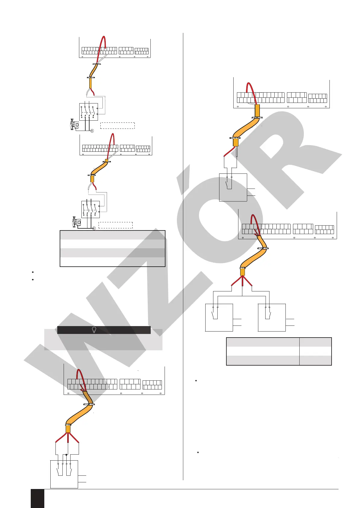
4) For Pumpc and DHW pipe pump:
KM3
Power supply
753 1
A1
A2
2468
KM7
Power supply
753 1
A1
A2
2468
�
�
����
CN11
25 26
1
2
3
4
5
6
7
8
9
10
CN7 CN30
27 28
29 30
31
32
9
21
�
�
����
CN11
25 26
1
2
3
4
5
6
7
8
9
10
CN7 CN30
27 28
29 30
31
32
12
24
Pumpc(zone2 pump)
P-d
DHW pipe pump
a) Procedure
Connect the cable to the appropriate terminals as shown in the picture.
Fix the cable reliably.
CN5
Control port signal type
Voltage
Maximum running current(A)
Wiring size(mm
2
)
Type 2
220-240VAC
0.2
0.75
Voltage
Maximum running current(A)
Wiring size(mm
2
)
220-240VAC
0.2
0.75
Room thermostat type 1(High voltage): "POWER IN" provide the working
voltage to the RT, doesn’t provide the voltage to the RT connector directly. Port
"15 L1" provide the 220V voltage to the RT connector. Port "15 L1" connect
from the unit main power supply port L of 1- phase power supply.
Room thermostat type 2(Low voltage) : "POWER IN" provide the working
voltage to the RT.
5) For room thermostat:
Method B
RT1
C
POWER
IN
H
Method A
RT1
POWER
IN
Room thermostat type 1 (High voltage):
Method C
RT1
POWER IN
RT2
POWER IN
3 15 4
�
�
����
CN11
25 26
1
2
3
4
5
6
7
8
9
10
CN7 CN30
27 28
29 30
31
32
15
34
�
�
����
CN11
25 26
1
2
3
4
5
6
7
8
9
10
CN7 CN30
27 28
29 30
31
32
15
3
�
�
����
CN11
25 26
1
2
3
4
5
6
7
8
9
10
CN7 CN30
27 28
29 30
31
32
15
34
L1
L1H
C
H
L1
There are two optional connect method depend on
the room thermostat type.
NOTE
There are three methods for connecting the thermostat cable (as described in the
picture above) and it depends on the application.
Method A
RT can control heating and cooling individually, like the controller for 4-pipe FCU. When
the hydraulic module is connected with the external temperature controller, user
interface FOR SERVICEMAN set ROOM THERMOSTAT to MODE SET:
A.1 When unit detect voltage is 230VAC between C and L1 ,the unit operates in the
cooling mode.
A.2 When unit detect voltage is 230VAC between H and L1, the unit operates in the
heating mode.
A.3 When unit detect voltage is 0VAC for both side(C-L1, H-L1) the unit stop working
for space heating or cooling.
A.4 When unit detect voltage is 230VAC for both side(C-L1, H-L1) the unit working in
cooling mode.
Method B
RT provide the switch signal to unit. User interface FOR SERVICEMAN set ROOM
THERMOSTAT to ONE ZONE:
B.1 When unit detect voltage is 230VAC between H and L1, unit turns on.
B.2 When unit detect voltage is 0VAC between H and L1, unit turns off.
zone1 zone2
(Mode set control)
(One zone control)
(Mode set control)
(One zone control)
(Double zone control)
Installation and operation manual - air-water heat pump Prima © All rights reserved - Galmet Sp. z o.o. Sp. K.134
 Loading...