RF340-4PR-ASL
Instruction Manual
WWW.GAMAINC.COM
Included in this Kit:
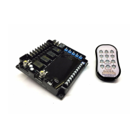
(1) RF340-4PR-ASL Receiver
(1) 12-Button Transmitter *Image shown with standard transmitter*
- Long Range Antenna LRA340 **SEE PAGE 3 FOR SETUP**
Available accessories:
- Additional Transmitter RFT340-4PR-TO
- Rechargeable Transmitter GKF-WPTX-12
- Waterproof Enclosure GWE-663-812
RF340-4PR-ASL is an RF Transmitter and Receiver operating at a fixed frequency of 340 MHZ. The receiver operates from 12VDC and provides
four polarity reversing outputs. Up to 30 transmitters can be programmed to activate the receiver. The receiver has terminal blocks for connecting
the input power and output to the 4-polarity reversing relay outputs. Each transmitter has a unique address that is transmitted when a button is
pressed. A “program” button is provided on the receiver to program the transmitter(s) address into the receiver’s memory. An LED on the receiver
indicates the receiver’s programming status and illuminates when the receiver is energized. The operating range is at least 100 feet.
The transmitter has two buttons assigned to each of the four outputs. The up(^) button runs the motor in one direction and the down (v) button
runs the motor in the opposite direction. The outputs are energized for as long as the buttons are depressed.
Manual Switch Input Control: The receiver contains a 10-position terminal block for connection to manual switch inputs to control the 4 polarity
reversing outputs. The manual switch inputs are logic level inputs and only require small gauge wire between the switches and the terminal block.
Current Detection/Over-Current System Shutdown: The RF340-4PR-ASL incorporates output current detection that will disconnect an output
when the output exceeds the current setting of the DIP switch for that output. When multiple outputs are activated, the total current of all active
outputs are monitored. The sum of the current for all outputs are shutdown for 5 seconds. After the 5 second reset time the output can be
activated by pressing the corresponding switch on the transmitter.
The system will monitor the current trip circuit and will allow the output to be activated 3-separate times when a current trip threshold occurs. After
the third consecutive current trip occurs within one-minute time period, the receiver will turn off all outputs and the program LED will start to flash.
The input power to the receiver must be turned off and then back on to re-activate the system. This is a safety feature to protect the receiver and
connected loads, and alerts the user there is an over-current condition that should be resolved.
Latching Light Output: There is a 2-position terminal block on the receiver that provides an output to a 12VDC light. The transmitter “LIGHT”
switch is used to control the light output. The output is rated at 10 Amps.
Maximum Ratings: Power for the receiver can be in the range of 10VDC to 15VDC. The receiver is reversing polarity protected. The relay
contacts are rated at 30 Amps @ 13.8VDC.
Power Consumption: 10mA when the relays are de-energized, 45mA when one relay is energized.
Dimensions: Receiver dimensions are approximately 5”L x 5”W x 2”H
Operating Temperature Range: 0°F to 160°F
Automated Time Out Adjustment: The automatic time out of the Receiver after last switch activation is adjustable from no time-out, up to 1-hour
time-out. The switch used to adjust the time-out set point is located on the Receiver and can be set for the time shown in the table on page 2.
Page 1 REV A 06/16/20
- Clear Protective Transmitter Pouch ZLB-67
- Hand-held Pendant HP4PR-ASL
- Package of 6 A23 12V Alkaline Batteries A23-6