Do you have a question about the Game Composites GB1 GameBird and is the answer not in the manual?
Provides conversions for length, volume, speed, pressure, torque, and temperature.
Details the aircraft's certification category and operating conditions.
Provides the name and address of the aircraft manufacturer.
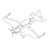
Presents a diagram showing the overall dimensions and views of the aircraft.
Describes the GB1's construction, cockpit, landing gear, airframe, wings, and mechanical systems.
Details the standard, optional, and not-available equipment installed on the aircraft.
Explains the EASA and FAA approved airworthiness limitations section.
Details requirements for component replacement based on operating time limits.
Outlines requirements for life-limited components and the airframe life limit.
Specifies the maximum allowable structure temperature and conditions for flight.
Provides information on time limits and minimum periodic inspection requirements for airworthiness.
Lists time limits (TBO) for major components like engine, magnetos, alternator, propeller, and governor.
Lists recommended replacement times for items like seat belts and fasteners based on condition.
Explains airworthiness directives and operator responsibilities for compliance with maintenance.
Details which panels can be removed for inspection and provides access information.
Provides inspection criteria and replacement criteria for various aircraft components.
Lists the required tasks for a 25-hour inspection, noting it's not required for spin-on oil filters.
Lists the required tasks for a 50-hour inspection, covering engine and various systems.
Lists additional items for the 100-hour inspection, including repeat of 25/50-hour tasks and specific checks.
Details the extensive disassembly and inspection required for the 1000-hour inspection.
Provides a log for recording flight hours, dates, organizations, and inspector initials for inspections.
Instructs to contact Game Composites if accelerometers indicate loads exceeding approved limits.
Outlines inspection procedures for damage after impacts, bird strikes, or ground incidents.
Details inspection procedures for hail damage, including tap-testing.
Specifies visual checks for structural damage after a hard landing.
Details inspection procedures for the propeller and engine mount after a propeller strike.
Outlines visual inspections for structural damage and system integrity after an engine bay fire.
Details inspection procedures for structural damage, metal parts, bearings, and electrical items after a lightning strike.
Describes using engine hoist lugs, wing tips, and tail lifting methods.
Details procedures for supporting the front and tail of the airplane for maintenance.
Outlines the steps to drain fuel, remove ballast, position scales, and calculate empty weight and CG.
Provides a table of weights and moment arms for various aircraft components used in CG calculations.
Provides guidance on securing the aircraft during short-term parking, including tie-down procedures.
Details measures for long-term storage, including tire pressure, engine protection, and battery maintenance.
Explains the function of placards and rules regarding their removal or alteration.
States there are no limitations for color choice but notes a restriction for the vertical stabilizer.
Lists and illustrates the part numbers and locations of exterior placards.
Lists and illustrates the part numbers and locations of interior placards.
Provides general information on servicing, recommending interval shortening for abnormal conditions.
Lists the specific tools required for airframe maintenance and servicing.
Mentions the use of metric fasteners in specific aircraft components.
Details the procedure for checking fuel drain valves before each flight.
Explains the refueling points and includes warnings about static electricity and fire hazards.
Provides instructions for defueling the aircraft's fuel tanks, including safety warnings.
Details how to check and top up the engine oil level, including suggested oil grades.
Outlines the procedure for changing the engine oil, including ground run and cowling removal.
Specifies the correct tire size and recommended pressure for the main landing gear.
Explains how to check, top-up, and bleed the brake fluid and includes a caution about brake fluid.
Provides instructions for cleaning the exterior surfaces and lights using automotive products.
Details the correct procedure for cleaning the canopy and windshield materials.
Advises checking and cleaning the interior before the first flight of the day.
Provides instructions for cleaning Multi-Function Display screens safely without damaging components.
Advises on safe methods for removing snow and ice to prevent damage.
Covers torque values, standard components, fasteners, sealants, and disassembly/shipping instructions.
Provides standard and special torque values for AN fasteners and bolt identification.
Describes the type of spherical bearings used, inspection criteria, and removal/installation procedures.
Explains the use of Adhesive Nutplates (Clickbond) and inspection criteria for replacement.
Details specifications and application methods for tank sealant, general adhesives, and Clickbond adhesive.
Outlines visual checks for hoses and fittings, replacement criteria, and installation notes.
Provides a step-by-step procedure for disassembling the aircraft for shipping.
Includes a drawing for a wing support box and notes on material and dimensions for outer wing support.
Details the steps for reassembling the aircraft after shipping, including checks and inspections.
Describes systems for internal and external communication via VHF, transponder, and ground stations.
Explains the operation of the VHF transceiver, its connection to MFDs, and its specifications.
Details the location, type, manufacturer, and replacement procedure for the VHF antenna.
Describes the location and replacement of MIC/PHONE jacks for connecting headsets.
Outlines the procedure for checking VHF performance after maintenance or replacement.
Provides an overview of the DC electrical system, load distribution, switches, and circuit breakers.
Details the electrical supply distribution via switches and circuit breakers, including component types.
Provides a wiring diagram overview and a table of wire loom components and their specifications.
Describes the alternator type, location, manufacturer, and service procedure, including ground run checks.
Details the battery type, location, manufacturer, and procedures for accessing, servicing, and connecting/disconnecting leads.
Describes the voltage regulator type, location, manufacturer, and service procedure, including ground run checks.
Explains the master relay's function and provides access and testing procedures.
Details the starter relay's function and provides access, testing, and replacement procedures.
Describes the optional external power socket, its location, and function check procedure.
Provides guidance for inspecting wires, harnesses, connectors, terminal blocks, grounding, and fuses.
Offers troubleshooting steps for various electrical system components, including battery, voltage regulator, master/starter relays, and boost pump.
Describes the design, operation, and adjustment of mechanical stick and rudder flight control systems.
Illustrates and lists components of the elevator and aileron control system.
Details the service or replacement procedure for the front control stick assembly.
Outlines the procedure for servicing or replacing the aft control stick assembly.
Provides instructions for removing and servicing the torque tube in both cockpits.
Details items to be removed to service the front torque tube bearing.
Describes the components of the aft torque tube bearing and servicing procedures.
Outlines the procedure for inspecting or servicing aileron control rods connecting to the torque tube.
Details how to inspect or service aileron control rods connecting the bellcrank to the aileron.
Provides steps for inspecting or servicing the aileron bellcrank and its bearings.
Outlines the procedure for inspecting or servicing the elevator control rod inside the torque tube.
Details how to inspect or service the elevator control rod connecting the torque tube to the idler.
Provides steps for inspecting or servicing the elevator control rod from the idler to the bellcrank.
Outlines the procedure for inspecting or servicing the elevator idler.
Details how to inspect or service the elevator bellcrank assembly.
Illustrates and lists components of the rudder control system.
Details the front seat rudder pedal assembly, including play limits and replacement advice.
Outlines the procedure for inspecting or servicing front seat rudder pedal adjusters.
Provides steps for inspecting or servicing the forward rudder bellcrank.
Details how to service the front right rudder interconnecting rod.
Describes servicing the front left rudder interconnecting rods.
Outlines the procedure for servicing the center rudder bellcrank mount.
Details servicing the center rudder bellcranks.
Provides steps for servicing the rear right rudder interconnecting rod.
Describes servicing the rear left rudder interconnecting rods.
Outlines the procedure for servicing the aft rudder bellcrank assembly.
Details servicing the aft rudder bellcrank mount.
Lists parts for the rear seat rudder pedal assembly and provides service instructions.
Outlines the procedure for servicing rear seat rudder pedal adjusters.
Details servicing the right-hand rudder cable, including tension adjustment.
Describes servicing the left-hand rudder cable.
Provides information on the jigs required for rudder cable rigging procedures.
Outlines the procedure for servicing the rudder bellcrank.
Explains how to uninstall front seat flight controls for weight reduction or passenger flights.
Details the procedures for reinstalling front seat flight controls, pedals, and engine controls.
Describes the fuel system components, capacity, fuel type, and tank locations.
Provides a schematic diagram of the aircraft's fuel system, showing components and flow.
Shows an overview of the Acrotank and details the procedure for servicing it.
Details the inspection procedure for the Acrotank flop tube, including removal and cleaning.
Outlines the inspection procedure for the wing tanks, including panel removal and sealant checks.
Describes the selector valve type, manufacturer, and servicing procedure, noting its fit.
Details the selector switch type, manufacturer, and servicing procedure, noting its fit.
Describes the fuel control torque rods and universal joints, including servicing procedures.
Details the boost pump type, manufacturer, servicing procedure, and function test.
Provides instructions for cleaning the Gascolator, including fuel selector switch position and leak checks.
Outlines the procedure for servicing the Acrotank fuel level sensor, including electrical connections and testing.
Details the wingtank fuel level sensor type, manufacturer, and servicing procedure.
Describes systems sensing environmental conditions and displaying flight data, including pitot-static system.
Explains the pitot and static system components, connections, and water draining procedures.
Lists the types of PVC hoses and connectors used in the pitot-static system.
Details how to service or replace the pitot tube assembly mounted on the wingtip.
Describes the procedure for testing the pitot-static system and connected instruments using a calibrated tester.
Provides a table of common pitot-static and airspeed indicator issues, their probable causes, and remedies.
Details the airspeed indicator type, manufacturer, scale, markings, and servicing procedures.
Describes the altimeter type, manufacturer, range, features, and servicing procedures for both cockpits.
Details the accelerometer type, manufacturer, range, and servicing procedures, including troubleshooting.
Provides instructions for compensating and correcting the magnetic heading indicator.
Describes the main landing gear, axles, hydraulic brakes, and non-structural composite fairings.
Explains that fairings are composite and refers to inspection and repair sections.
Details the procedure for removing and servicing the left main gear leg.
Outlines the procedure for removing and servicing the right main gear leg.
Describes the tailwheel assembly, its mounting, steering mechanism, and maintenance requirements.
Provides a step-by-step procedure for removing and servicing the tailwheel spring.
Details the procedure for servicing the tailwheel, including wheel nut, axle, and parts replacement.
Explains how to inspect and replace brake pads without removing the wheel, including installation steps.
Details caliper inspection, repair, and reinstallation procedures, including cautions on brake fluid.
Provides a drawing and parts list for the brake assembly.
Outlines the procedure for servicing the axle, including cleaning, inspection, and torque values.
Details wheel assembly removal, disassembly, inspection, and reassembly procedures.
Provides steps for inspecting the axle, installing the wheel, mounting the tire, and reassembling the wheel.
Describes the anti-collision and position light assemblies, troubleshooting, and replacement procedures.
Details the landing/recognition light units, their control, troubleshooting, and replacement.
Covers systems providing position information from ground installations, including transponder and GPS.
Explains transponder capabilities, ADS-B Out/In, FIS-B, and GPS signal functions.
Details the transponder antenna location, type, manufacturer, and service procedure.
Outlines the location, type, manufacturer, and servicing procedure for the GPS antenna, including function check.
Describes the instrument panels and headrest, their installation, and composite structure.
Details how to service the rear instrument panel, including disconnects and inspections.
Explains how to remove and service the headrest, noting restrictions for antenna reception.
Outlines the procedure for servicing the front instrument panel, including removal and component checks.
Provides an overview of the Garmin G3X system, its components, functions, and maintenance.
Displays a schematic showing the interconnections of the Garmin G3X avionics system components.
Explains the use of SD cards for database updates, checklists, and data logging in the G3X Touch system.
Details how to obtain and update navigation databases for the G3X Touch system.
Provides general troubleshooting steps for the avionics system, focusing on physical inspection and connections.
Lists approved instrument markings and their limitations for engine and fuel indications.
Explains which components are activated by the Battery Master and Avionic Master switches.
Describes how system failures are indicated (e.g., red 'X') and the expected initialization time.
Refers to the Garmin G3X Touch Installation Manual for system usage instructions.
Details the MFD 1 type, manufacturer, location, servicing procedure, and screen cleaning.
Describes MFD 2 type, manufacturer, location, servicing procedure, and screen cleaning.
Details the Magnetometer type, manufacturer, location, servicing procedure, and calibration.
Describes the ADAHRS unit type, manufacturer, location, servicing procedure, and calibration.
Outlines the Engine Data Converter type, manufacturer, location, and servicing procedure.
Details the OAT probe type, manufacturer, location, and servicing procedure, including function checks.
Describes the RPM sensor type, manufacturer, location, and servicing procedure.
Outlines the Fuel Pressure Sensor type, manufacturer, location, and servicing procedure.
Details the Fuel Flow Transducer type, manufacturer, location, and servicing procedure.
Describes the Ammeter Shunt type, manufacturer, location, and servicing procedure.
Outlines the CHT Sensor type, manufacturer, location, and servicing procedure.
Details the EGT Sensor type, manufacturer, location, and servicing procedure.
Describes the Manifold Pressure Sensor type, manufacturer, location, and servicing procedure.
Outlines the Oil Pressure Sensor type, manufacturer, location, and servicing procedure.
Details the Oil Temperature Sensor type, manufacturer, location, and servicing procedure.
Mentions the removable ballast weight and its purpose for CG adjustment.
Provides instructions for installing the removable ballast weight into the fuselage chamber.
Outlines the steps for removing the ballast weight and cover.
Describes the tap test method for checking composite structures for delamination.
Provides information on investigation, classification, and repair of structural damage, emphasizing approved methods.
Classifies damage to composite parts into categories (Class 1-4) with associated warnings.
Lists composite materials used, including epoxy resin, carbon fiber, glass fiber, honeycomb, and filler materials.
Details general composite repair practices, personal equipment, tools, and environmental conditions.
Explains how to repair minor surface damage on composite structures, including chamfering and laminate build-up.
Details the procedure for repairing sandwich damage, including trimming, inner laminate repair, and outer skin repair.
Provides guidance on repairing stripped threads in composite structures using resin/flocks mix.
States that spar damage is Class 1 and must be reported to Game Composites.
Lists various adhesives, sealants, and coatings used in composite repairs, with specifications.
Details the preparation and application of paint to repaired areas.
Lists paint materials for exterior and interior applications, including body fillers, primers, and top coats.
States steel parts should be replaced, not repaired.
States aluminum parts should be replaced, not repaired.
States titanium parts should be replaced, not repaired.
States additive manufactured parts should be replaced, not repaired.
Provides instructions for cleaning canopy glasses using water and soft cloths, with warnings against dry wiping.
Details the procedure for removing the windshield, including fastener removal and hinge pin manipulation.
Outlines the steps for removing the canopy, including support and disconnection of its components.
Describes the procedure for removing, cleaning, inspecting, and reinstalling canopy hinges.
Lists parts for the canopy lock assembly and provides a diagram.
Details the procedure for inspecting or servicing the interconnecting rod for the canopy.
Outlines the procedure for servicing the aft canopy handle.
Describes the procedure for servicing the front canopy handle.
Provides a detailed procedure for replacing the windshield and canopy glass, including preparation and bonding.
Describes the horizontal stabilizer as a composite assembly bonded into the fuselage.
Details the procedure for servicing the elevators, including removal, cleaning, and inspection.
Outlines the procedure for servicing the elevator trim tab, including deflection checks.
Describes the elevator trim servo type, manufacturer, and servicing procedure, including function checks.
Specifies the allowable free play for the elevator relative to the stabilizer.
Details the procedure for weighing the elevators individually and checking their balance.
Outlines the procedure for servicing the rudder, including deflection and weight & balance checks.
Describes the wing construction, spar system, ribs, fuel tanks, and surface protection.
Details the procedure for servicing the aileron assembly, including linkage disconnection and neutral position adjustment.
Outlines the procedure for servicing the aileron trim tab, including deflection checks.
Describes the aileron trim servo type, manufacturer, and servicing procedure.
Explains the installation and uninstallation of removable carbon fiber sight gauges at the wing tips.
Refers to Lycoming manuals for engine information and describes the oil system and firewall sealing.
Details the procedure for servicing the cowling, including removal, cleaning, and inspection of fasteners.
Describes the engine mount structure and provides detail views of attachment points and hardware.
Provides a detailed step-by-step procedure for removing the engine from its mount.
Details the procedure for reinstalling the engine, including connecting controls and performing ground runs.
Outlines the tasks required for removing the engine mount, including supporting the fuselage and removing landing gear.
Details how to service the engine cooling plenum, including cowling removal and inspection.
Describes the engine shock mount type, manufacturer, and replacement procedure.
States that the engine controls do not require regular maintenance but components must be replaced if defective.
Provides diagrams illustrating the throttle quadrant assemblies and their components.
Lists part numbers and descriptions for throttle, propeller, and mixture control cables and their fittings.
Details the installation and adjustment procedures for the control cables and quadrants.
Refers to section 40 for details on engine monitoring functions and components in the Garmin G3X Touch System.
Details the Annunciator Lights Panel, its location, manufacturer, servicing, and troubleshooting for LEDs.
Describes the oil cooler type, manufacturer, location, and servicing procedure, including checks for leaks.
Provides a table listing part numbers, types, manufacturer numbers, fittings, angles, and lengths for oil lines.
Explains the Christen inverted oil system, its gravity operation, and components like the oil separator and gravity valve.
Describes the smoke system components, tanks, pump, oil lines, and operation.
Specifies the approved oil type for the smoke system and provides handling and safety information.
Details the smoke pump relay type, manufacturer, location, servicing, and function test.
Describes the check valve type, manufacturer, location, servicing, and refill/draining procedures.
Lists the specification for the refill hose used in the smoke system.
Outlines the filling, draining, and system testing procedures for the smoke system.
| Type | Light Sport Aircraft |
|---|---|
| Manufacturer | Game Composites |
| First flight | 2015 |
| Status | In production |
| Crew | 1 |
| Capacity | 1 |
| Engine | Rotax 912 ULS |
| Horsepower | 100 hp (75 kW) |
| Service ceiling | 15, 000 ft (4, 600 m) |
| Gross weight | 1, 320 lb |
| Powerplant | Rotax 912 ULS |
| Propellers | 3-bladed |
| Range | 500 nautical miles (580 mi; 930 km) |