Use and Maintenance Manual – Pressure-sensitive bumpers type GSBPS 24/35
9.3 Wire connection
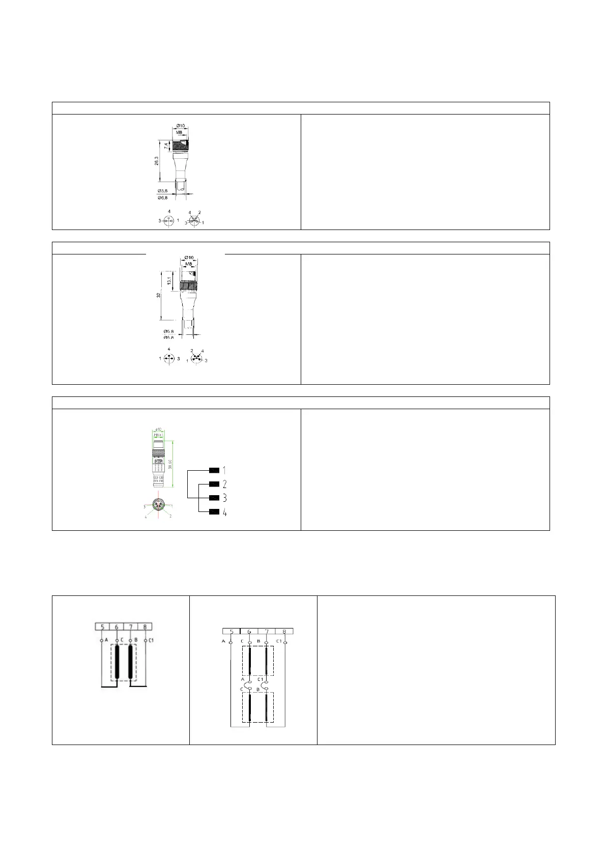
Wire connection to the connector 4 pole
Pin 1 - Brown wire ( C )
Pin 2 - White wire ( C1)
Pin 3 - Blue wire ( A )
Pin 4 –Black wire ( B )
Pin 1 - Brown wire ( A )
Pin 2 - White wire ( B )
Pin 3 - Blue wire ( C )
Pin 4 –Black wire ( C1 )
GSCMCM8 – Connector for electric circuit closing Male M8
Pin 1 - Brown wire ( A )
Pin 2 - White wire ( B )
Pin 3 - Blue wire ( C )
Pin 4 –Black wire ( C1 )
Wires connection without connector
In case the sensors have the cable without connector, the wire connection must be made by using the proper terminal
complies with local regulations.
Exemple of wires connection with sensor and Gamma System control unit (see the manual of Unit control device))
A (wire brown) - C1(wire black)
Power sensor
C (wire blue) –B (wire black)
Fedback sensore
Connection diagram of
Two bumpers
A (wire brown) Power sensor
B (wire black) Feedback sensor
C (wire blue) Sensor 1 in serie with A(wire brown) Sensor 2
C1(wire black) Sensor 1 in serie with B(wire black) Sensor 2
C (wire blue) Feedback sensor
C1(wire black) Power sensor