RESET / FEEDBACK GP02R
Automatic Reset
Without feedback : Link terminals 10 and 14. Insert JP2 between B and C inside the card.
With feedback : Connect the feedback circuit between terminals 10 and 14. Insert JP2 between B and C inside the card
Manual Reset
Without feedback : Link reset contact (N.O.) between terminals 10 and 14. Insert JP2 between A and B inside the card
With feedback : Connect the feedback circuit on series of reset contact (N.O.) between terminal 10 and 14.
Insert JP2 between A and B inside the card
RESET / FEEDBACK GP02R-C
Automatic Reset
Without feedback : Link terminals 5 and 6. Insert JP1 between B and C inside the card.
With feedback : Connect the feedback circuit between terminals 5 and 6. Insert JP1 between B and C inside the card
Manual Reset
Without feedback : Link reset contact (N.O.) between terminals 5 and 6. Insert JP1 between A and B inside the card
With feedback : Connect the feedback circuit on series of reset contact (N.O.) between terminal 5 and 6. Insert JP1
between A and B inside the card
Bridge inside the card.
M A B C
A B C
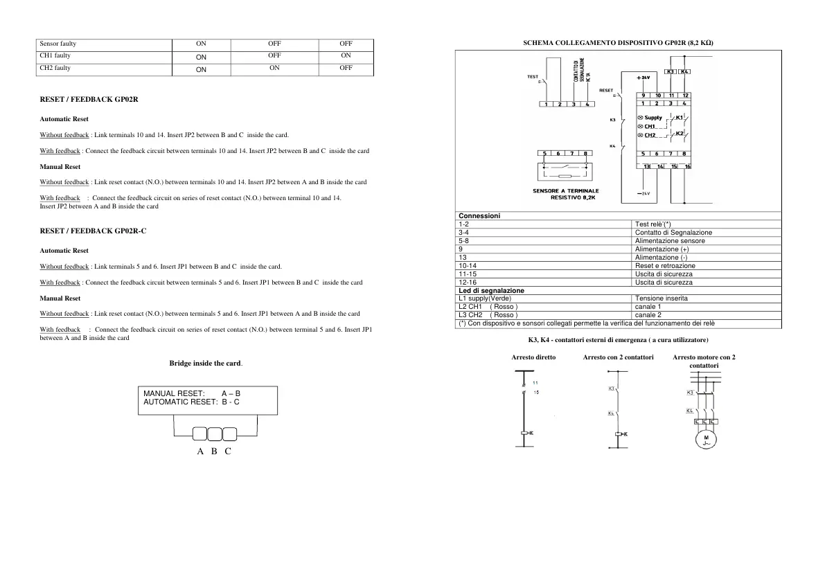
SCHEMA COLLEGAMENTO DISPOSITIVO GP02R (8,2 KΩ)
K3, K4 - contattori esterni di emergenza ( a cura utilizzatore)
 Loading...