EasyManuals Logo

GAMMA SYSTEM GP02R User Manual

Default Icon
6 pages
To Next Page IconTo Next Page
To Previous Page IconTo Previous Page
Page #4 background imageLoading...
Page #4 background image
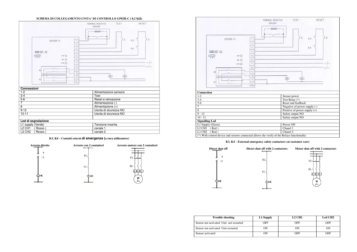
SCHEMA DI COLLEGAMENTO UNITA’ DI CONTROLLO GP02R-C ( 8,2 KΩ)
Connessioni
1-2
Alimentazione sensore
3-4
Test
5-6
Reset e retroazione
7
Alimentazione (-)
8
Alimentazione (+)
9-12
Uscita di sicurezza NO
10-11
Uscita di sicurezza NO
Led di segnalazione
L1 supply (Verde)
Tensione inserita
L2 CH1 ( Rosso )
canale 1
L3 CH2 ( Rosso )
canale 2
K3, K4 Contatti esterni di emergenza (a cura utilizzatore)
Arresto diretto
Arresto con 2 contattori
Arresto motore con 2 contattori
Connection
1-2
Sensor power
3-4
Test Relay (*)
5-6
Reset and feedback
7
Negative of power supply (-)
8
Positive of power supply (+)
9 - 12
Safety output NO
10 - 11
Safety output NO
Signalling Led
L1 Supply (Green)
Power ON
L2 CH1 ( Red )
Chanel 1
L3 CH2 ( Red )
Chanel 2
(*) With control device and sensors connected allows the verify of the Relays functionality
K3, K4 External emergency safety contactors (at customer care)
Trouble shooting
L1 Supply
L2 CH1
Led CH2
Sensor not activated Unit not restarted
OFF
OFF
OFF
Sensor not activated Unit restarted
ON
ON
ON
Sensor activated
ON
OFF
OFF
Direct shut off
Direct shut off with 2 contactors
Motor shut off with 2 contactors

Questions and Answers:

Question and Answer IconNeed help?

Do you have a question about the GAMMA SYSTEM GP02R and is the answer not in the manual?

GAMMA SYSTEM GP02R Specifications

General IconGeneral
BrandGAMMA SYSTEM
ModelGP02R
CategoryControl Unit
LanguageEnglish

Related product manuals