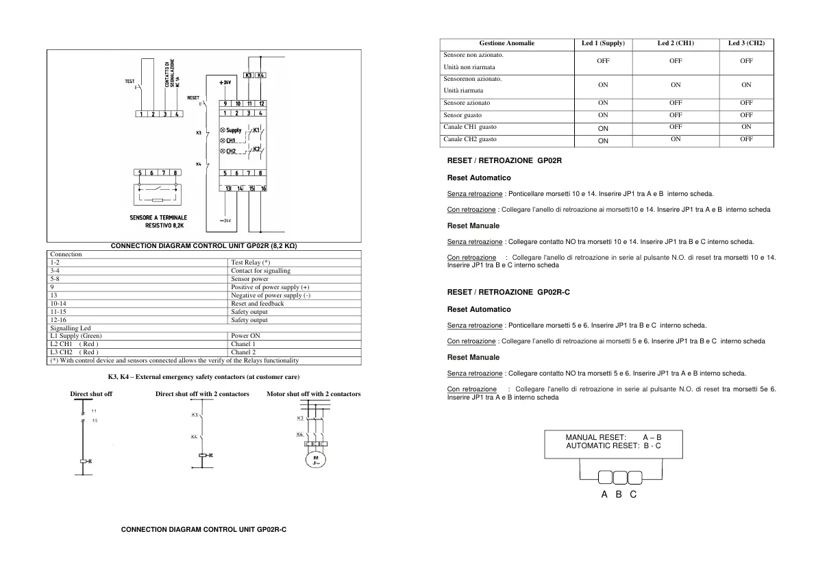
K3, K4 – External emergency safety contactors (at customer care)
CONNECTION DIAGRAM CONTROL UNIT GP02R-C
RESET / RETROAZIONE GP02R
Reset Automatico
Senza retroazione : Ponticellare morsetti 10 e 14. Inserire JP1 tra A e B interno scheda.
Con retroazione : Collegare l’anello di retroazione ai morsetti10 e 14. Inserire JP1 tra A e B interno scheda
Reset Manuale
Senza retroazione : Collegare contatto NO tra morsetti 10 e 14. Inserire JP1 tra B e C interno scheda.
Con retroazione : Collegare l'anello di retroazione in serie al pulsante N.O. di reset tra morsetti 10 e 14.
Inserire JP1 tra B e C interno scheda
RESET / RETROAZIONE GP02R-C
Reset Automatico
Senza retroazione : Ponticellare morsetti 5 e 6. Inserire JP1 tra B e C interno scheda.
Con retroazione : Collegare l’anello di retroazione ai morsetti 5 e 6. Inserire JP1 tra B e C interno scheda
Reset Manuale
Senza retroazione : Collegare contatto NO tra morsetti 5 e 6. Inserire JP1 tra A e B interno scheda.
Con retroazione : Collegare l'anello di retroazione in serie al pulsante N.O. di reset tra morsetti 5e 6.
Inserire JP1 tra A e B interno scheda
M A B C
A B C
 Loading...