EasyManua.ls Logo

Gammaflux TTC - User Manual

Gammaflux TTC
4 pages
Print Icon
To Next Page IconTo Next Page
Loading...
TTC
International interface
Advanced Setup/Troubleshooting
Version 2.0
English
450
C
449
TTC Scrolling
Errors
1
2
Row Scrolling
Select zones to scroll
Press both view area select and enter together
Selected rows will scroll
View zone(s) in a group
View rows automatically
Zone Scrolling
Select zones to scroll
Press both change area select and enter together
Selected zones will scroll
View zone(s) in a group individually
Change Area View AreaView Area
Select
Select
Enter
C
E-1
Power Up Error
E-0 = No zones found
E-1 = Configuration mismatch
Solutions (Change Area – Enter)
Instruct the interface to do one of the following:
1 – Read configuration from system (recommended)
2 – Send configuration to system from interface
3 – Locate zones (zone finder)
Menu Load Error
E-2 = Menu mismatch, will not load, press enter to clear
Gammaflux
Sterling, VA USA Tel. +1-(703) 471-5050
Wiesbaden, Germany Tel. +49-(0)-611-973430
Ube, Japan Tel. +81-(836) 54-4369
Singapore Tel. +65-901-83710
www.gammaflux.com; www.gammaflux.de
Question and Answer IconNeed help?

Do you have a question about the Gammaflux TTC and is the answer not in the manual?

Summary

TTC Scrolling

Row Scrolling

Select zones to scroll and press both view area select and enter together for rows to scroll automatically.

Zone Scrolling

Select zones to scroll and press both change area select and enter together for zones to scroll individually.

Error Codes

Power Up Errors

Details power-up error codes like E-0 (no zones found) and E-1 (configuration mismatch).

Menu Load Errors

Explains menu mismatch errors (E-2) and the procedure to clear them.

Interface Operation Areas

Row;Group Selection

Covers row selection, row alarm status, and group selection (All/Custom).

View and Change Areas

Displays actual values, deviations, and allows boost/standby operations.

Zone Select;Status

Indicates selected zones and manual/percentage operation status.

Alarm Conditions

Temperature Alarms

Details high and low temperature alarms with default deviation settings.

Thermocouple Issues

Covers T/C open, reversed, or pinched conditions for accurate readings.

Heater;Output Issues

Addresses open fuses, shorted/open heaters, and uncontrolled outputs.

Advanced Setup Guide

Setup Configuration

Explains restoring/saving mold setups and individual zone configurations.

Parameter Settings

Details settings for boost, standby, tuning, alarms, and limits.

Security and System Codes

Covers security level access, zone finder activation, and LED tests.

Basic Troubleshooting

Alarm Area Troubleshooting

Guides on diagnosing T/C, heater, and output issues based on alarm indicators.

General Troubleshooting Steps

Provides steps for checking resistance of T/C, heaters, and cables.

Module;Controller Issues

Details how to identify bad modules or controller-related problems.

Overview

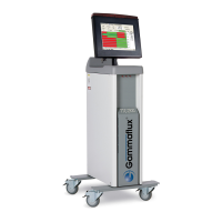
The Gammaflux TTC International interface is a sophisticated control system designed for advanced setup and troubleshooting in industrial applications, particularly those involving temperature control. This device allows for precise management of multiple zones, offering both automatic and manual control options, and incorporates a comprehensive error detection and diagnostic system.

Function Description

The TTC International interface serves as a central control unit for managing temperature zones. It enables users to monitor and adjust various parameters, including temperature set points, output percentages, and alarm thresholds. The system is designed to operate with high accuracy and reliability, providing real-time feedback on zone status and performance.

The core functionality revolves around two primary scrolling modes:

  • Row Scrolling: This mode allows users to select and view multiple zones within a group simultaneously. When activated, selected rows scroll automatically, providing a quick overview of the status of several zones.
  • Zone Scrolling: This mode enables individual viewing and adjustment of zones within a group. Users can select specific zones to scroll through them one by one, allowing for detailed inspection and fine-tuning of each zone's parameters.

The interface supports both automatic and manual temperature control. In automatic mode, the system maintains a set temperature, while in manual mode, users can directly control the percentage of power output to a zone. Advanced features like "Boost" allow for temporary temperature increases, and "Standby" mode provides a controlled temperature reduction for material protection or remote input.

Important Technical Specifications

The device is equipped with a clear digital display that shows actual temperature values, percentage output, and deviation from the automatic set point. Temperatures can be displayed in either Celsius or Fahrenheit. The system includes various alarm indicators for critical conditions such as high/low temperature, thermocouple issues (open, reversed, pinched), open fuses, shorted/open heaters, and uncontrolled output.

Key specifications and configurable limits include:

  • Boost Temperature Set Point: Adjustable from +/-100°F/55°C (default 20°F/11°C), defining the amount of temperature added during a boost.
  • Boost Time Set Point: Configurable from 0-300 seconds (default 60 seconds), determining the duration of the boost.
  • Temperature Deviation Alarm Set Point: Activates individual zone alarms at a configurable +/- set point (default -31 to 27).
  • Standby Set Point: Adjustable from 0-1000°F/537°C (default 220°F/104°C), used for material protection or remote input.
  • Automatic Set Point Limit: Defines the maximum set point an operator can enter in automatic mode (default 0-1000°F/537°C).
  • Manual Set Point Limit: Defines the maximum set point an operator can enter in manual mode (default 0-100% output).
  • Trim Limit: Specifies the maximum amount of degrees an operator can permanently change the zone(s) during a trim (default 0-1000°F/537°C).
  • T/C Pinched Detection Time: Configurable from 0 to 54.0 minutes (default 5 minutes), determining the duration before a pinched thermocouple alarm is triggered.
  • Critical Over Temperature Alarm: If the temperature exceeds a set threshold for 8 seconds, all zones in automatic mode are turned "Off."
  • Power Priority™: Configurable from 0-4, increasing smoothing of power output.
  • Temperature Units: Selectable between Degree F and Degree C.
  • Thermocouple Type: Selectable between Type J and Type K.
  • Zone Power Status on Power Up: Configurable to "all zones turned Off" or "zones On when shut down last, stay On."
  • Security Levels: The system supports multiple security levels (0-2) to restrict access to advanced settings.

The physical interface includes various connectors for thermocouples, power input/output, auxiliary input/output, and communication modules. It features a main disconnect, ground lug, and a fan for cooling.

Usage Features

The TTC International interface is designed for ease of use while offering extensive customization.

  • Group Selection Area: Allows users to create and store custom zone groups, in addition to an "All Group" option that selects all zones in the system. This feature simplifies managing multiple zones with similar requirements.
  • Zone Select/Status Area: Provides individual zone selection and status indicators, showing whether a zone is in manual or automatic operation, and highlighting alarms.
  • Advanced Setup: Accessible by pressing both select buttons simultaneously, this mode allows users to configure detailed operational parameters, including boost settings, standby temperatures, alarm thresholds, and security codes.
  • Configuration Management: Users can read configurations from the system, send configurations to the system from the interface, or locate zones (zone finder) to identify new hardware.
  • LED Test: A diagnostic feature that turns on all LEDs for troubleshooting.
  • Software Version Display: The interface can display software version numbers for output modules, T/C input modules, data concentrators, and operator panels, aiding in system maintenance and updates.

Maintenance Features

The system incorporates several features to facilitate troubleshooting and maintenance:

  • Error Reporting: The "Errors" section on the display provides clear indications of issues such as "Power Up Error" (E-0 for no zones found, E-1 for configuration mismatch) and "Menu Load Error" (E-2 for menu mismatch).
  • Troubleshooting Guide: The manual provides a step-by-step guide for general troubleshooting, starting with checking resistance at the mold for thermocouples and heaters, then checking cable connections, and finally isolating issues to specific modules.
  • Alarm Area Indicators: A dedicated alarm area visually indicates various fault conditions, such as open/reversed/pinched thermocouples, open fuses, shorted/open heaters, and uncontrolled output.
  • Module-Level Diagnostics: The system allows for checking fuses on individual modules and swapping modules to diagnose faults.
  • Component Identification: A detailed diagram of the internal components helps users identify specific parts like output modules, thermocouple input modules, data concentrators, and power supplies, which is crucial for targeted repairs or replacements.
  • Contact Information: Gammaflux provides contact information for support in various regions (USA, Germany, Japan, Singapore) for further assistance or spare parts.

The TTC International interface is a robust and versatile control system, offering comprehensive features for precise temperature management, advanced configuration, and efficient troubleshooting in demanding industrial environments.

Gammaflux TTC Specifications

General IconGeneral
BrandGammaflux
ModelTTC
CategoryTemperature Controller
LanguageEnglish