Befestigung des Oberteils
In diesem Abschnitt wird beschrieben, wie die Montage durch Aufstecken des
Oberteils und der RFID-Leserabdeckung abgeschlossen wird. Bevor Sie diese
Schritte ausführen, schließen Sie zuerst die Anschlusskabel an. Lesen Sie dazu
die Hinweise in Abschnitt “Elektrischer Anschluss“ auf Seite 5.
ACHTUNG! Elektrischer Schlag. Der Anschluss muss im span nungslosen
Zustand erfolgen.
HINWEIS! Achten Sie darauf, dass die Elektronik und Printplatte des GT7 bei
der Montage nicht beschädigt oder verkratzt wird.
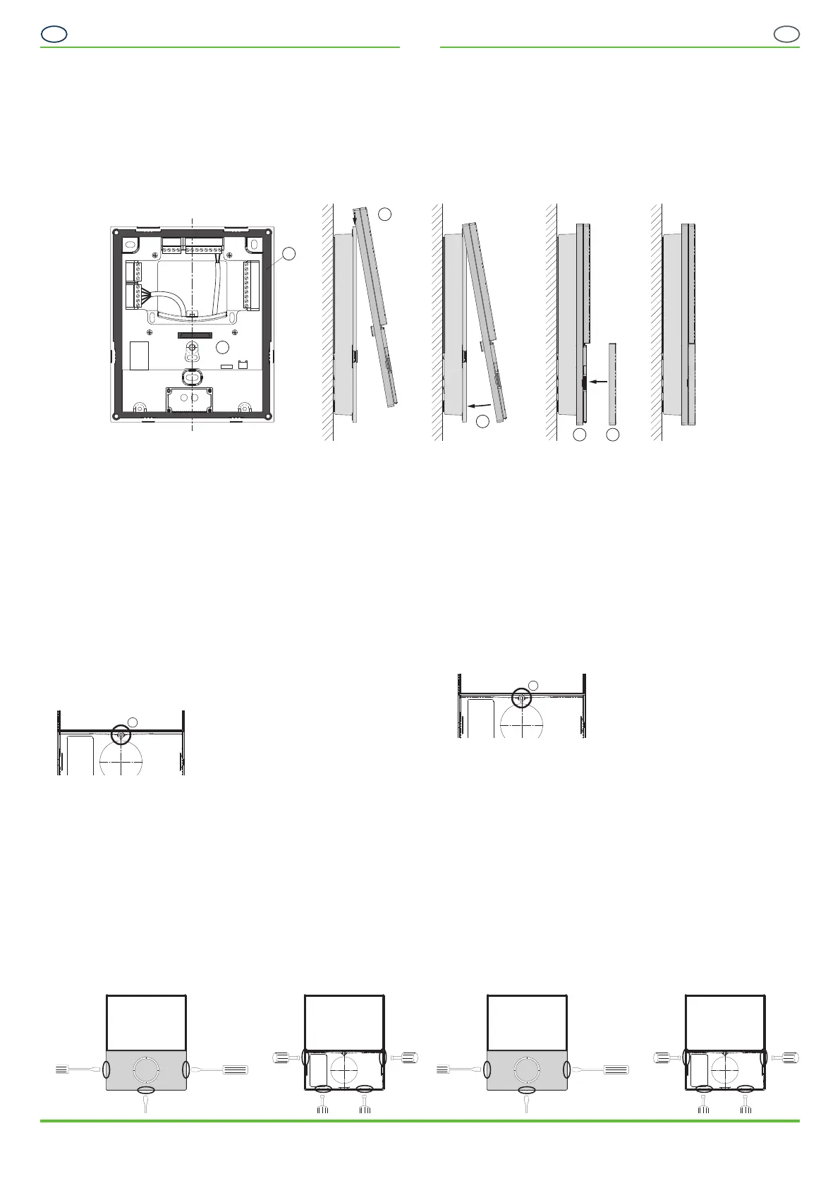
1. Kontrollieren Sie, dass die am inneren Rand des Oberteils eingelegte
Dichtung (8) und der zentrale Verbindungsstecker (9) sauber und
unbeschädigt sind.
ACHTUNG! Benutzen Sie keine Flüssigkeiten zur Reinigung.
2. Haken Sie das Oberteil mit den 2 Laschen an der Oberseite des Unterteils
ein (10).
3. Klappen Sie das Oberteil auf das Unterteil (11).
4. Drücken Sie das Oberteil mit leichtem Druck auf das Unterteil, bis es in den
Laschen um den Rand des Unterteils einrastet (12).
Üben Sie nicht zu viel Druck aus. Sollte das Aufstecken nicht ohne starken
Krauftaufwand möglich sein, kontrollieren Sie die Laschen und den zentralen
Verbindungsstecker und wiederholen Sie den Vorgang.
HINWEIS! Mit diesem Prozess wird auch das Oberteil mit dem Unterteil
elektrisch über den zentralen Verbindungsstecker (9) verbunden.
HINWEIS! Das Oberteil muss bündig mit dem Unterteil abschließen (siehe
rechtes Bild oben) und festen Halt haben.
5. Drehen Sie die Befestigungsschraube (13) in das Oberteil, um dieses fest mit
dem Unterteil zu verbinden.
6. Stecken Sie die RFID-Leserabdeckung (6) auf das Oberteil auf. Es rastet mit
3 Laschen ein.
HINWEIS! Die Leserabdeckung muss bündig mit dem Oberteil ab-
schließen und festen Halt haben.
Öffnen des Gehäuses
Sollte das Gehäuse z. B. zur Verkabelungs änderung oder für Servicezwecke
geöffnet werden müssen, gehen Sie wie folgt vor:
1. Lösen Sie die RFID-Leserabdeckung mit einem Schlitz-Schraubendreher an
den 3 seitlichen Laschen und nehmen Sie die Abdeckung ab.
2. Drücken Sie an den vier im folgenden Bild gekennzeichneten Schlitzen im
Gehäuseoberteil die Ränder nach außen, so dass sich die Laschen darunter
lösen und nehmen Sie das Oberteil vom Unterteil ab.
RFID-Leserabdeckung lösen Oberteil lösen
Attaching the Front Part
This section describes how to complete the installation by attaching the front
part and RFID reader cover. Before completing these steps, first connect the
connection cables. For more information, read the “Electrical Connections” section
on page 5.
CAUTION! Electrical shock. The electrical connections must be made in a
de-energized state.
NOTE! Make sure that the electronics and printed circuit board of the GT7 are
not damaged or scratched during assembly.
1. Check that the gasket (8), which is inserted in the inner edge of the front
part, and the central connector (9) are clean and undamaged.
CAUTION! Do not use liquids for cleaning.
2. Hook the 2 tabs of the front part over the top of the rear part (10).
3. Swing the front part forward onto the rear part (11).
4. Gently press the front part onto the rear part until it snaps into the tabs
around the edge of the rear part (12).
Do not exert too much pressure. If the front part cannot be attached without
great effort, check the tabs and the central connector and repeat the process.
NOTE! Through this process, the front part is electrically connected to the
rear part via the central connector (9).
NOTE! The front part must sit flush with the rear part (see picture above)
and be securely attached.
5. Tighten the fixing screw (13) into the front part to firmly attach it to the rear
part.
6. Attach the RFID reader cover (6) to the front part. It locks into place via 3
tabs.
NOTE! The reader cover must sit flush with the front part and be securely
attached.
Opening the housing
Should the housing need to be opened, e.g., for cabling modifications or servicing,
proceed as follows:
1. Release the RFID reader cover using a flat-blade screwdriver on the 3 side
tabs and remove the cover.
2. On the 4 slots in the front part as indicated in the picture below right, press
the edges outwards so that the tabs underneath release and remove the front
part from the rear part.
Release RFID reader cover Release front part
DE
EN
VB_GT7-2500-3500--DE+EN_11 • Art.Nr.: 1100341
Gültig ab 9. August 2018
Technische Änderungen vorbehalten!
Seite 4
VB_GT7-2500-3500--DE+EN_11 • Part No.: 1100341
Valid as of 9
th
August, 2018
Technical data subject to modification without notice!
Page 4
GANTNER Electronic GmbH
Montafonerstr. 8 • 6780 Schruns/Austria
T +43 (0)5556 73784 • info@gantner.com • www.gantner.com
8
9
10
11
12 6
13
13

 Loading...