DE
EN
VB_GT7-2500-3500--DE+EN_11 • Art.Nr.: 1100341
Gültig ab 9. August 2018
Technische Änderungen vorbehalten!
Seite 5
VB_GT7-2500-3500--DE+EN_11 • Part No.: 1100341
Valid as of 9
th
August, 2018
Technical data subject to modification without notice!
Page 5
GANTNER Electronic GmbH
Montafonerstr. 8 • 6780 Schruns/Austria
T +43 (0)5556 73784 • info@gantner.com • www.gantner.com
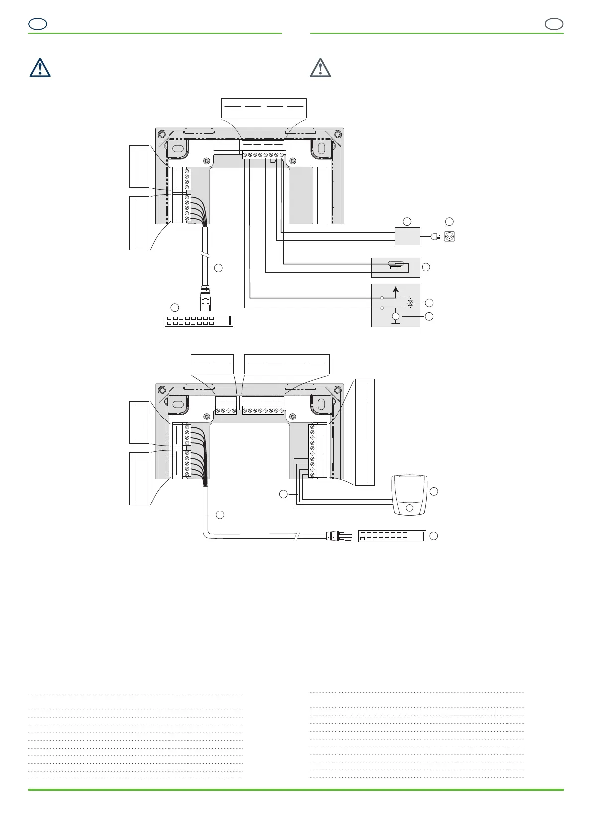
Elektrischer Anschluss
ACHTUNG! Elektrischer Schlag. Trennen Sie immer die Versor-
gungsspannung, bevor Sie elektrische Verbindungen ändern.
Anschlussbeispiel GT7.2500
Anschlussbeispiel GT7.3500
1 ...... Netzwerk (TCP/IP)
2 ...... Ethernet-Switch
3 ...... PoE-Switch
4 ...... Netzteil
5 ...... Netzspannungsanschluss
6 ...... Elektrischer Rückmeldekontakt
7 ...... Freilaufdiode
8 ...... Motorsteurung mit externer Versorgung
9 ...... Leserschnittstelle
10 ...busfähiger, externer Leser (z. B. GAT SR 7xxx oder GAT SLR 7xxx Serien)
Netzwerk (Ethernet)
Verbinden Sie das Ethernet-Kabel an einem eigenen Port des Netzwerk-Switch.
Der für alle Ethernet-Verbindungen empfohlene Kabeltyp ist min. CAT 5 (STP) für
100 MBit. Die Aderfarben sind wie folgt:
Klemme Signal Adernfarbe
TIA-568A
Adernfarbe
TIA-568B
RX
-
Empfangssignal RX
-
grün orange
RX+ Empfangssiganal RX+ grün/weiß orange/weiß
TX
-
Sendesignal TX
-
orange grün
TX+ Sendesignal TX+ orange/weiß grün/weiß
Shld Schirm - -
DC+ PoE Versorgung + blau/weiß blau/weiß
DC+ PoE Versorgung + blau blau
DC
-
PoE Versorgung - braun/weiß braun/weiß
DC
-
PoE Versorgung - braun braun
Electrical Connections
CAUTION! Electrical shock. Always disconnect the power supply
before altering electrical connections.
Connection example GT7.2500
Connection example GT7.3500
1 ...... Network (TCP/IP)
2 ...... Ethernet switch
3 ...... PoE switch
4 ...... Power supply
5 ...... Mains voltage connection
6 ...... Electric feedback contact
7 ...... Freewheeling diode
8 ...... Motor control with external supply
9 ...... Reader interface
10 ...Bus-capable, external readers (e.g., GAT SR 7xxx or GAT SLR 7xxx Series )
Network (Ethernet)
Connect the Ethernet cable to a separate port on the network switch. The
recommended cable type for all Ethernet connections is min. CAT 5 (STP) for 100
Mbps. The wire colors are as follows:
Terminal Signal Wire Color
TIA-568A
Wire Color
TIA-568B
RX
-
Receive signal RX
-
green orange
RX+ Receive signal RX+ green/white orange/white
TX
-
Send signal TX
-
orange green
TX+ Send signal TX+ orange/white green/white
Shld Shield - -
DC+ PoE Supply + blue/white blue/white
DC+ PoE Supply + blue blue
DC
-
PoE Supply - brown/white brown/white
DC
-
PoE Supply - brown brown
ETHERNET
Shld
TX+
TX
-
RX+
RX
-
ETHERNET PoE
DC
-
DC
-
DC+
DC+
Rel. 2 VOut 2
NO
C
GND
24 V
Rel. 2 VOut 2
NO
C
GND
24 V
VOut 1Rel. 1
NO
C
GND
24 V
Opto VIn
IN
-
IN+
GND
24 V
Wieg.
5V
CLK
DATA
GND
RX
TX
RS-485RS-232
GND
B
V
OUT
(24V)
A
Wieg.
5V
CLK
DATA
GND
RX
TX
RS-485RS-232
GND
B
OUT
(24V)
A
1
9
10
3
ETHERNET
Shld
TX+
TX
-
RX+
RX
-
VOut 1Rel. 1
NO
C
GND
24 V
Opto VIn
IN
-
IN+
GND
24 V
ETHERNET PoE
DC
-
DC
-
DC+
DC+
ETHERNET
Shld
TX+
TX
-
RX+
RX
-
VOut 1Rel. 1
NO
C
GND
24 V
Opto VIn
IN
-
IN+
GND
24 V
1
N S
VOut+
GND
4 5
2
6
7
8
VOut 1Rel. 1
NO
C
GND
24 V
Opto VIn
IN
-
IN+
GND
24 V
M
ETHERNET PoE
DC
DC
DC+
DC+
ETHERNET
Shld
TX+
TX
-
RX+
RX
-
ETHERNET PoE
DC
-
DC
-
DC+
DC+
 Loading...