Do you have a question about the Garaventa Lift GSL Artira and is the answer not in the manual?
| Brand | Garaventa Lift |
|---|---|
| Model | GSL Artira |
| Category | Lifting Systems |
| Language | English |
Critical safety warnings, personal protective equipment, electrical, and mechanical precautions.
Procedures for handling high voltage and electrical safety.
Precautions for working with moving parts and heavy components.
Procedures for inspecting the lift upon delivery and handling shipping damage.
Instructions for safely removing packaging materials from the lift.
Importance and availability of the GSL Artira Spare Parts Kit.
Preparation steps, including tool kit, lift knowledge, and checking packages.
Initial steps to start the installation process, including reading notes and moving the drive cabinet.
Guidance on positioning the lift tubes and using shims for elevation.
Steps for temporarily supporting tube sections on a wall.
Steps for assembling tube sections using support towers.
Instructions for connecting tube sections using splices, ensuring proper fit and alignment.
Placing the drive cabinet and aligning upper tube ends.
Instructions for checking and verifying landing clearances with lift drawings.
Final checks on landing clearances and splice alignment for system fit.
Procedures for drilling and fastening towers to stair treads, including anchor types.
Illustrations of typical mounting methods for towers, including wall and backing plate connections.
Detailed steps for installing drive ropes and levers for the standard drive system.
Instructions on connecting rope splices within the tube system and securing the drive cabinet.
Steps for installing drive ropes and levers for the compact drive system.
Instructions for removing the drive cog cover and mounting the drive assembly.
Connecting wiring between the drive, control box, and terminal block according to schematics.
Instructions for connecting the main power to the drive cabinet and ensuring safety.
Detailed wiring instructions for lift safety circuits and call stations, referencing diagrams.
Steps for lifting and attaching the conveyance onto the installed tube system, requiring assistance.
Instructions for installing conical rollers on the lower carriage using thread locking compound and grease.
Visual guide and steps for lubricating and installing shoulder bolts for lower conical rollers.
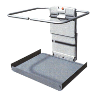
Procedures for unlocking and unfolding the Artira platform, with safety notes.
Connecting ramp linkages and installing the lift arms onto their shafts.
Wiring the conveyance power and sliding contact connections through the carriage cover.
Mounting and connecting call stations, considering clearance and local codes.
Overview of the Call Station PCB, terminal strip, and troubleshooting indicators.
Pre-power-on checks and steps to safely turn on the lift system.
Explanation of drive PCB indicators when the system is at rest and ready for operation.
Initial conditions and steps for performing the lift setup procedure.
Process for assigning call stations and landings during the setup phase.
Detailed steps for establishing the lower landing position and adjusting cams.
Procedures for assigning call stations to specific landings and managing folding options.
Instructions for completing setup when safety circuits are not engaged, requiring bypass.
Key notes and conditions requiring completion of the setup procedure, including troubleshooting.
Procedure for resetting landing positions without re-assigning stations, initiated via PCB.
Steps to initiate the landing reset procedure using the Drive PCB buttons.
Verifying platform, ramps, and arms folding functions and travel clearances.
Performing lift inspection tests, providing training, and completing the handover process.
Concluding statement on the successful completion of the installation.
A comprehensive list of tools required for the installation of the GSL Artira lift.
Detailed specifications of the GSL Artira lift, including load, speed, and power requirements.
Record of revisions and updates made to the installation manual over time.
Explanation of standard component symbols used in Garaventa electrical schematics.
Details on the operation of lamps on the Call Station and their various modes like Initialization.
Explanation of the SEEK operation and assigning call stations to landings.
Description of normal call station operation and error indicators.
Details on the operation of lamps on the conveyance indicating status.
Explanation of conveyance lamp modes: Initialization, Normal, and Errors.
How conveyance lamps indicate safety violations or E-Stop activation.
A chart listing fasteners and their usage for different components in the installation.
