10
EN
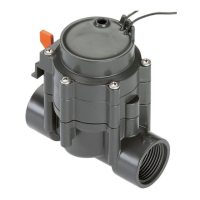
Assemble the Irrigation Valve
9V / 24 V (Art. 1251 / 1278):
Connecting Watering
Valves 24 V (Art. 1278):
H
G
H
F
D
0 B 7C8
9
E
Art. 1280
E
Art. 1280
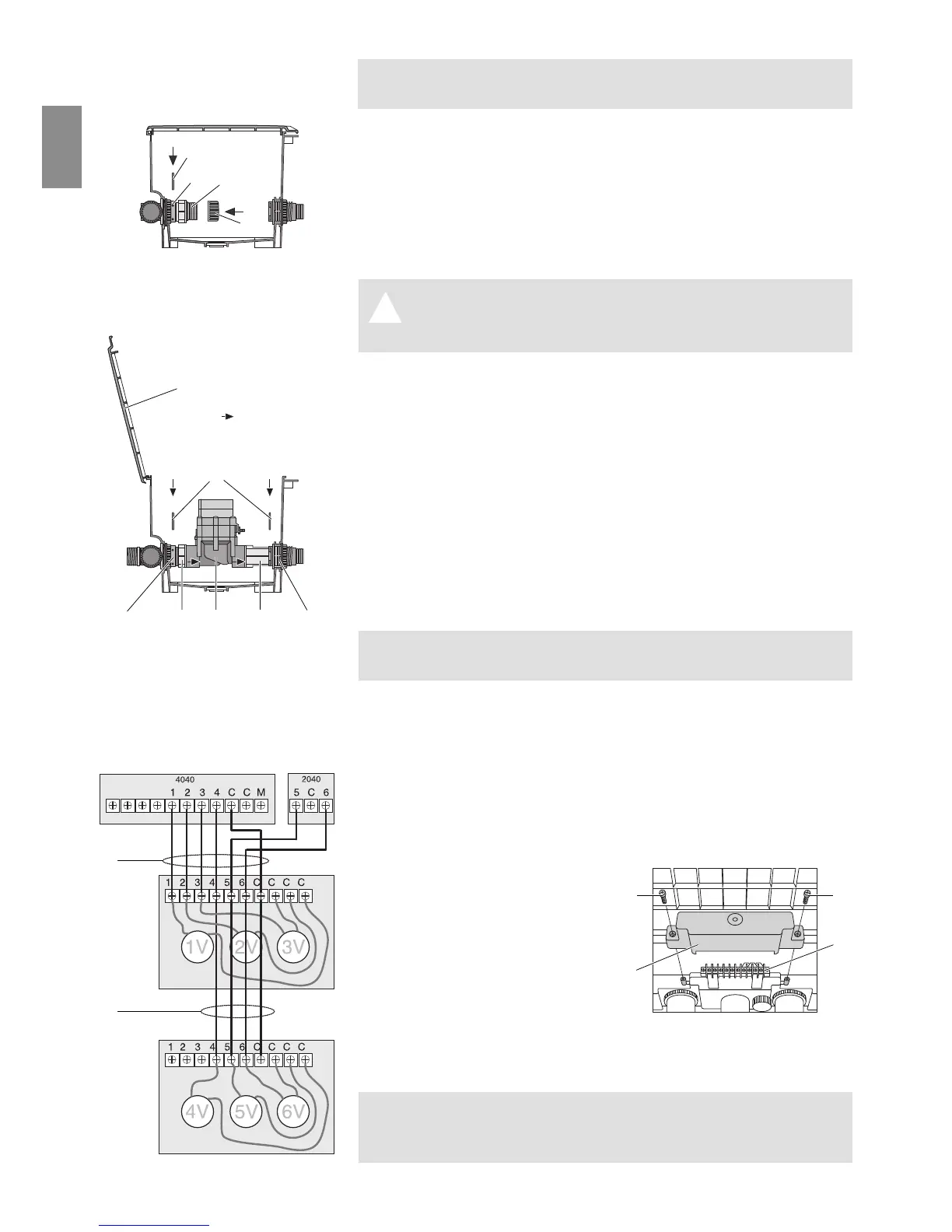
V3: Close open distributor
output:
A
8
0
9
If you are only installing 2 valves in a Valve Box V3, the open
distributor output must be sealed with an end cap.
1. Push the short telescopic pipe
8
into the open distributor
output.
2. Insert the securing clip
9
into the holes of the distributor
output
0
.
The flushing pipe
8
is fixed in place.
3. Screw the cover cap
A
onto the short telescopic pipe
8
.
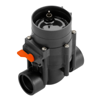
Attention! Flow direction!
A V Pay attention to the flow direction (arrows) when
assembling the Irrigation Valve
C
.
1. Push the long telescopic pipe
B
all the way into the nipple
on the outlet-side
7
.
2. Screw the short telescopic pipe
8
into the inlet side of the
Irrigation Valve
C
.
The arrows on the Irrigation Valve point in
the flow direction.
3. Push the Watering Valve with the short telescopic pipe
8
into
the distributor output
0
.
4. Screw the long telescopic pipe
B
into the outlet-side of the
Irrigation Valve
C
.
5. Insert the securing clip
9
into the holes of the distributor out-
puts
0
and the connections
7
.
The telescopic pipes
8
/
B
are fixed in place.
When you open the box lid
D
you can see the flow direction
marked by the arrows on the Irrigation Valve
C
.
You can connect up to 12 Watering Valves Art. 1278 (24 V) to the
Watering Controller 4040 Art. 1276 using the Connection Cable Art.
1280 in combination with the expansion module 2040 Art. 1277.
1. Guide the connection cable
E
into the side of the Valve Box V3
and attach to the terminal strip
F
according to the outputs of
the watering controller (refer to colour of cable).
2. Screw one cable from each valve into the connections C.
3. Screw the other cable from
each valve into the connec-
tions 1– 6 according to the
routing of the cables.
4. If you are using 2 Valve
Boxes of model V3, connect
the second Valve Box V3 to
the first Valve Box V3 using
the connection cable.
5. Push the protective cap
G
over the terminal strip
F
and tighten
both screws
H
.
Please refer to the operating instructions for the Programming
Unit Art. 1242 for instructions on how to connect the Watering
Valves Art. 1251 (9V) to the Controllers Art. 1250.