EasyManua.ls Logo

Gardner Bender 960 Series - User Manual

Gardner Bender 960 Series
2 pages
Print Icon
To Next Page IconTo Next Page
Loading...
Gardner
Bender
Back-to-Back Bend
90˚ Bend
“Dog Leg” Bend or “Kick”
Leg Length
Offsets
Rise or “Stub-ups”
Segment Bend
Concentric Bends
6
1. ARROW
Indicates start of bend. Use for stubs and
saddle bends.
2. RIM NOTCH
Locates center of saddle bend.
3. STAR
Indicates the back of a 90° bend.
4. ANGLE ARROWS
Indicates the angle when bending on the
floor. (sighting down the bender)
5. DEGREE SCALES
Indicates the angle when bending in the
air. (sighting in-line with the conduit)
6. BEND BACK
Special channel designed for
correcting overbends.
7. CONDUIT VISE
Clamps conduit during cutting.
5
3
2
4
7
BENDING NOTES:
Thread handles into bender head as far as
they will go.
BENDING ON THE FLOOR:
For best results keep the conduit pinned to
the floor by applying constant pressure on
the foot pedal throughout the entire bend.
BENDING IN THE AIR:
Tuck the conduit under your
arm and use your foot to
keep the handle from
sliding on the floor. Keep
your hands and body
close to the bender
throughout the bend.
CORRECTING OVER BENDS:
There are two options for correcting
over-bends. One option uses the open
end of the handle as a “cheater” bar and
the second uses the hook area.
OPTION 1
OPTION 2
1
Benfield
®
Style Hand Bender
How to Bend Guide
960 Series Benders
For instructions in Spanish and French please visit
Por favor, para instrucciones en Español y Francés visite
Pour des instructions en espagnol et français, veuillez visiter
www.gardnerbender.com
Question and Answer IconNeed help?

Do you have a question about the Gardner Bender 960 Series and is the answer not in the manual?

Summary

960 Series Bender Guide

Bender Component Overview

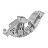
Identifies key parts of the bender like arrow, rim notch, star, angle arrows, degree scales, bend back, and conduit vise.

General Bending Techniques

Provides essential tips for effective bending on the floor, in the air, and correcting overbends.

Specific Bend Type Instructions

90° or Stub Bends

Step-by-step guide for measuring, marking, and executing 90° or stub bends on conduit.

Back to Back Bends

Instructions for measuring and marking conduit for back-to-back bends using the bender's indicators.

Saddle Bends

Procedure for bending conduit to go around obstructions, creating saddle bends with specific angles.

Offset Bends

Guide for creating offset bends to navigate obstructions, including measurement adjustments and angle multipliers.

Overview

The Gardner Bender Benfield® Style Hand Bender (960 Series) is a manual conduit bending tool designed for various electrical conduit installations. It is engineered to create precise bends in EMT, Rigid, and IMC conduits, facilitating the routing of electrical wiring around obstacles and into enclosures. The bender head features several marked indicators and scales to guide users through different bending operations, ensuring accuracy and consistency.

Function Description:

The primary function of the Gardner Bender 960 Series Hand Bender is to shape electrical conduit to specific angles and configurations required for installation. It achieves this by leveraging mechanical force applied by the user to deform the conduit around a curved shoe. The bender is capable of performing a variety of common bends, including:

  • Back-to-Back Bends: Used to create two 90-degree bends in opposite directions, often for routing conduit along a wall and then turning it back parallel to the wall.
  • 90° Bends (Stub-ups): Essential for creating right-angle turns, such as bringing conduit up from the floor or out from a wall.
  • "Dog Leg" Bends or "Kicks": Small, shallow bends used to offset conduit slightly, often to align with a box or another conduit run.
  • Leg Length Bends: Refers to the straight section of conduit after a bend, which is critical for precise installations.
  • Offsets: Used to move conduit from one plane to another, typically to clear an obstruction or enter a panel box. These involve two opposing bends.
  • Rise or "Stub-ups": Similar to 90° bends, specifically referring to the vertical rise of conduit.
  • Segment Bends: A series of small, incremental bends used to create a large radius curve.
  • Concentric Bends: Multiple bends of different radii, often used when several conduits need to follow a parallel curve.
  • Saddle Bends: Complex bends designed to go over obstructions like pipes, typically involving a center bend and two outer bends.

Important Technical Specifications & Features:

The bender head is equipped with several key indicators and features to aid in accurate bending:

  • ARROW (1): Indicates the starting point for bends, particularly useful for stub and saddle bends.
  • RIM NOTCH (2): Locates the center of a saddle bend, ensuring proper alignment for the central bend.
  • STAR (3): Indicates the back of a 90° bend, crucial for back-to-back measurements.
  • ANGLE ARROWS (4): Provide visual cues for the bending angle when the bender is on the floor, allowing the user to sight down the bender for alignment.
  • DEGREE SCALES (5): Allow users to identify the bending angle when working in the air, by sighting in-line with the conduit.
  • BEND BACK (6): A specialized channel designed for correcting overbends, providing a method to slightly reduce the angle of a bend that has gone too far.
  • CONDUIT VISE (7): Integrated into the bender head, this feature clamps the conduit during cutting, enhancing safety and precision.

Usage Features:

The manual provides detailed instructions for various bend types, emphasizing precision and technique:

  • Bending on the Floor: For optimal results, users are instructed to keep the conduit "pinned to the floor" by applying constant pressure on the foot pedal throughout the bend. This technique helps maintain stability and accuracy.
  • Bending in the Air: When bending in the air, the conduit should be tucked under the user's arm, and the foot used to prevent the handle from sliding. Keeping hands and body close to the bender is recommended for control.
  • Correcting Over Bends: Two options are provided for correcting over-bends:
    • Option 1: Using the open end of the handle as a "cheater" bar to apply leverage.
    • Option 2: Utilizing the hook area of the bender for correction.
  • 90° or Stub Bends: Involves measuring the stub height (x), subtracting a specific deduct amount (provided in a chart for different conduit sizes and types), marking the conduit, and aligning the mark with the arrow on the bender.
  • Back-to-Back Bends: Requires measuring the distance from a fixed point (x) to the back of the 90° bend (Y), marking the conduit, and aligning the mark with the star on the bender.
  • Saddle Bends: A multi-step process for navigating obstructions:
    1. Measure the obstruction's height/diameter (D).
    2. Measure the distance (L) to the obstruction and add 3/16" per inch of object height.
    3. Mark this distance (C) as the center point on the conduit.
    4. Calculate outer bend marks (X and Y) at 2.5 times the object size from the center mark.
    5. Align the center mark (C) with the "notch" for a 45° bend.
    6. Align outer marks (X and Y) with the arrow for 22.5° bends.
    • An alternative method uses a 60° center bend and two 30° outer bends.
  • Offset Bends: Commonly used for panel box entry or clearing obstructions:
    1. Measure the offset height (Z).
    2. Measure the distance to the obstruction (L) and add a "shrink amount" (from a chart) per inch of offset. Mark this on the conduit (X).
    3. Calculate (Z * angle multiplier) and subtract this from the first mark, marking the conduit again (X).
    4. Align the marks with the arrow to make the bends. A chart provides constant multipliers and shrinkage amounts for various bend angles (10°, 21.5°, 30°, 45°, 60°).

Maintenance Features:

While specific maintenance instructions are not explicitly detailed, the design implies durability and ease of use. The robust construction of the bender head, including the conduit vise, suggests a tool built for longevity in demanding work environments. The ability to thread handles into the bender head indicates a modular design that allows for secure assembly and potentially replacement of components if needed. The "Bend Back" channel serves as an integrated correction mechanism, reducing the need for external tools or re-bending, which contributes to the tool's overall efficiency and user convenience. The availability of instructions in multiple languages (Spanish and French) via the Gardner Bender website indicates a commitment to broad user support and accessibility.

Gardner Bender 960 Series Specifications

General IconGeneral
BrandGardner Bender
Model960 Series
CategoryTools
LanguageEnglish