Do you have a question about the Gardner Denver STP 125 and is the answer not in the manual?
Details the pump's operational limits for viscosity, speed, and temperature.
Specifies that the pump must only be used for its intended purpose and within set limits.
Addresses potential high sound pressure levels and the need for hearing protection.
Covers electrical, hydraulic, and temperature control supply needs for the pump.
Key operational safety rules, including observing technical data and avoiding common hazards.
Safety rules for electrical connection and correct pump operation during installation.
Safety guidelines for servicing, including power isolation and securing the pump.
Information on handling hazardous materials, including basic first aid for contamination.
Details hazards associated with materials like silicone sealant, anti-seize compounds, and paints.
Instructions for checking delivery documents and inspecting the pump for transit damage.
Guidance on using correct lifting gear and techniques for pump weight.
Recommendations for storing the pump if not installed immediately, including environmental conditions.
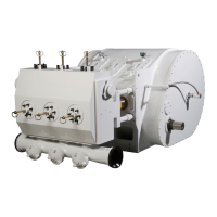
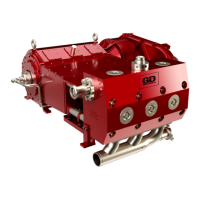
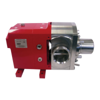
Describes the pump as a positive displacement rotary type, with trilobe rotors.
Explains how the trilobe rotors draw product in and discharge it based on rotation direction.
Provides detailed dimensional drawings and specifications for the horizontally ported pump.
Lists pump weights and its displacement per revolution.
Presents a chart with pump model, max flow rate, pressure, speed, and temperature limits.
Details the integral relief valve, its function, preset pressure, and causes of over-pressurisation.
Provides recommendations for system design, including NPSH, suction lines, and non-return valves.
Explains that flow direction is determined by drive shaft rotation.
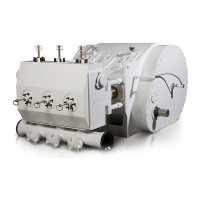
Describes how pump mounting feet can be changed for horizontal or vertical port orientation.
Details how to fill the gearbox with the correct oil level for horizontal and vertical ports.
Lists recommended lubricant brands and grades for the pump's gearbox.
Specifies the schedule for the first and subsequent oil changes for the gearbox.
Provides oil capacity for the pump based on porting (horizontal/vertical).
Specific warning and procedure for cleaning pumps equipped with a relief valve.
Advises on installing pressure gauges and outlines weekly checks for oil level and seals.
Lists essential spare parts recommended for maintenance and spares inventory.
Lists the tools required for dismantling the pump head and gearbox.
Crucial safety steps before starting disassembly: purging, isolation, closing valves, and disconnection.
Instructions for removing rotor nuts, stopping rotor turning, and extracting rotors from shafts.
References sections for 'O' ring and Mechanical seal removal procedures.
Steps to remove rotorcase retaining nuts and detach the rotorcase from the bearing housing.
Steps for removing the gear housing, bearing races, and timing gears.
Instructions for disassembling shafts from the bearing housing and removing bearing sets.
Detailed steps for fitting shafts, bearings, and bearing nuts into the bearing housing.
Instructions for cleaning and fitting rear retainers and applying silicone sealant.
Steps for fitting timing gears, keys, shims, and locking washers.
Steps for cleaning, heating, and fitting the gear housing, ensuring correct alignment and torque.
References sections for 'O' ring and Mechanical seal fitting procedures.
Instructions for aligning rotors, lubricating nuts, tightening nuts, and checking clearances.
Steps for fitting the front cover 'O' ring, cover, and ensuring correct torque.
Procedure for removing and replacing the product 'O'ring from the pump front.
Steps for fitting new 'O' rings into the seal housing, using water for lubrication.
Instructions for removing gland guards, cleaning the seal area, and levering out the seal housing.
Procedure for fitting the seal housing into the rotorcase, ensuring correct alignment.
Describes the components and working principle of a single mechanical seal.
Steps for removing gland guards, cleaning, and levering out seal components.
Provides dimensional drawings for the pump heating tank.
Procedure for safely removing the heating tank, including relieving pressure.
Steps for fitting the heating tank, ensuring clean faces, correct torque, and pipework connection.
Steps for safely disassembling the relief valve, including removing nuts and spring assembly.
Procedure for assembling the relief valve, fitting diaphragm, spring, and housing.
| Brand | Gardner Denver |
|---|---|
| Model | STP 125 |
| Category | Water Pump |
| Language | English |