Page 52
Part # MCOSM06 Rev 1 (11/03/08)
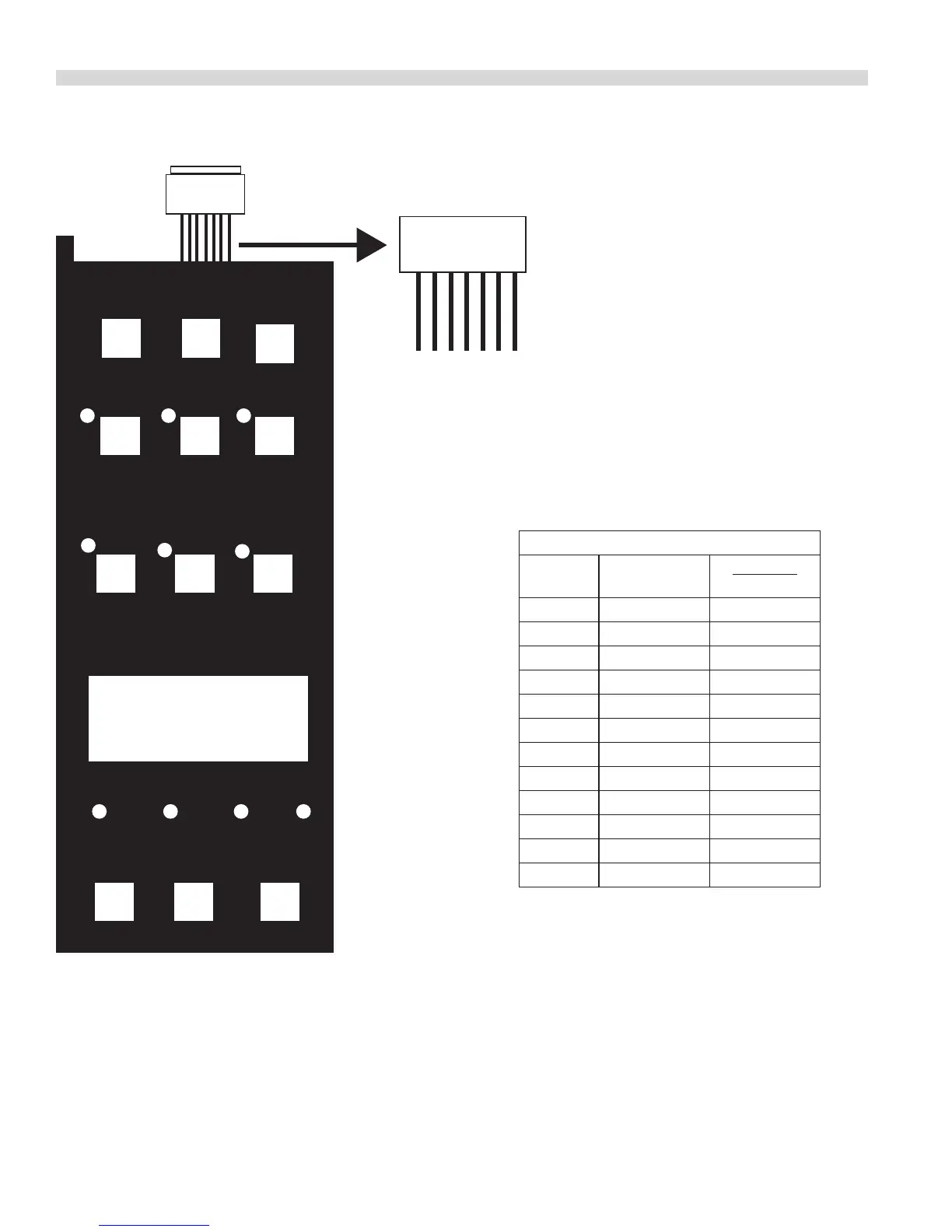
KEY PAD TEST
Key
#9
Key
#5
Key
#1
Key
#10
Key
#6
Key
#2
Key
#12
Key
#8
Key
#4
Key
#11
Key
#7
Key
#3
DISPLAY
Ribbon
Connector
PIN DETAIL
VIEWED FRON FRONT
PIN NUMBERS
On Ribbon
Connector
7 6 5 4 3 2 1
KEYPAD & TEST
POINTS VIEWED
FRON FRONT
PIN- OUT TEST POINTS
Key # PIN-OUTS
OVERLAY
MARKINGS
1 1 & 4 SET BACK
2 1 & 5 COOL DOWN
3 1 & 6 PROGRAM
4 1 & 7 ACTUAL TEMP
5 2 & 4 CAVITY LIGHT
6 2 & 5 FAN LOW
7 2 & 6 COOK / HOLD
8 2 & 7 SET
9 3 & 4 ON / OFF
10 3 & 5 FAN HIGH
11 3 & 6 PULSE
12 3 & 7 START/CANCEL
Between the above pin test points on the ribbon connector,
there should be continunty when the corresponding key is
pressed.
EXAMPLE: When Key # 1 is pressed and held, there should be
continunity between pins 1 & 4 at the ribbon cable.
NOTE: The keypad must be attached to the control panel
bezel when tested. The keypad is grounded to the panel to
complete the circuit. Disconnec the ribbon connector from
the SMART BOARD / CONTROLLER to gain better access to
teest points.
Not all overlays will have the above-indicated markings.
 Loading...