Do you have a question about the Garmin GA 56W and is the answer not in the manual?
Details on selecting an unobstructed location for the antenna, and separation from other antennas.
Guidance on doubler plate requirements for antenna support and structural integrity.
Specifies requirements for the conductive ground plane and its size.
Instructions for ensuring proper antenna grounding via mounting hardware.
Step-by-step instructions for installing the antenna, including sealant use.
Lists the unit and catalog part numbers for the GA 56W antenna and installation kit.
Provides the weight specifications for the antenna and installation kit.
Details WAAS electrical characteristics including frequency, gain, noise, supply, and antenna patterns.
Information on obtaining the GA 56W Environmental Qualification Form.
States that the GA 56W is compliant with TSO C144.
Guidance on TSO approval requirements and aircraft installation approval procedures.
States that the antenna maintenance is on-condition; no periodic maintenance is required.
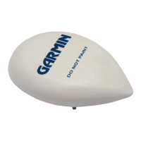
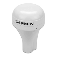
The GA 56W is a GPS antenna designed for aviation applications, featuring an integrated preamplifier that enhances signal reception. This antenna is specifically intended for use with GPS receivers that require an external preamplifier, providing robust performance for aircraft navigation systems. Its primary function is to receive GPS signals, which are then processed by the connected receiver to determine the aircraft's position, velocity, and time.
For optimal performance, the GA 56W antenna must be mounted on the top surface of the aircraft. When selecting a mounting location, it is crucial to ensure an unobstructed view of the sky, especially when the aircraft is in level flight. This placement minimizes signal blockage from aircraft structures such as vertical fins, T-tails, or dorsal fins, ensuring consistent and reliable GPS signal acquisition. The antenna should be positioned at least three feet away from transmitting antennas, including those for VHF Comm, HF transmitters, DME, Transponders, and Radar, to prevent interference. Additionally, it should be at least six inches away from receive-only antennas like other GPS or XM antennas. Careful routing of the antenna cabling is also important; it should not be run near cables associated with transmitting antennas to maintain signal integrity.
Installation of the GA 56W antenna requires careful planning and adherence to specific guidelines to achieve desired performance and reliability. A doubler plate is necessary when mounting the antenna on any unsupported skin area of the aircraft to provide adequate structural support, considering a maximum drag load of 5 lbs at subsonic speeds. It is critical not to weaken the aircraft structure when choosing a mounting area, and installers should consult aircraft manufacturer specifications and advisory circulars for appropriate guidance. Antenna performance is further improved by ensuring an adequate ground plane, which should be a conductive surface at least eight inches in diameter. For aircraft with fabric or composite skins, a ground plane, typically made of aluminum sheet or wire mesh, is recommended and usually installed beneath the aircraft skin.
The antenna is grounded through its mounting hardware, which includes washers and nuts. These components, along with the doubler plate, must make contact with an unpainted surface to ensure proper antenna grounding. Good conductivity between the coaxial shield and the ground plane is essential, achieved when all fasteners properly ground the antenna base to the aircraft skin.
The physical installation process involves drilling or punching holes according to the provided mounting cutout. After installing any required doubler plate, a gasket (Garmin part number 253-00002-00) is placed on the aircraft skin, aligning with the screw holes. The antenna is then secured using four supplied #8-32 stainless steel nylon locking nuts (Garmin part number 210-10004-09, or equivalent). These nuts must be torqued evenly across all mounting studs to prevent deformation of the mounting area. It is vital to ensure continuous contact between the antenna base and the aircraft skin with the gasket in between. Finally, the antenna and gasket are sealed to the fuselage using a good quality electrical grade sealant. A bead of sealant should be run along the edge where the antenna meets the exterior aircraft skin, taking care to avoid contaminating the antenna connectors with sealant. A crucial caution during this step is to avoid using construction-grade RTV sealant or any sealants containing acetic acid, as these can damage the electrical connections and potentially void the antenna warranty.
For installations on pressurized cabin aircraft, FAA-approved design and engineering substantiation data are required if the installation involves altering (penetrating) the cabin pressure vessel. Installers are advised to obtain approved design data from the aircraft manufacturer, an FAA-approved STC, or consult FAA Designated Engineering Representatives (DERs) for assistance in preparing and approving the necessary engineering data.
The GA 56W antenna is compliant with TSO C144, indicating it meets minimum performance standards. However, TSO articles require separate approval for installation in an aircraft, and such installations must be performed under 14 CFR Part 43 or applicable airworthiness requirements. The responsibility lies with the installing agency to ensure that the aircraft installation conditions meet TSO standards.
Regarding maintenance, the GA 56W antenna is designed for "on-condition" maintenance, meaning periodic maintenance is not required. This simplifies the operational upkeep of the antenna, as it only needs attention if a specific issue arises.
The product comes with a two-year limited warranty from the date of purchase, covering defects in materials or workmanship. During this period, Garmin will, at its sole discretion, repair or replace any failing components at no charge, with the customer responsible for transportation costs. The warranty explicitly excludes failures due to abuse, misuse, accident, or unauthorized alteration or repairs. This warranty is exclusive and in lieu of all other warranties, express or implied, including those of merchantability or fitness for a particular purpose. Garmin's liability for incidental, special, indirect, or consequential damages resulting from the use or inability to use the product is limited. To obtain warranty service, customers should contact their local Garmin Authorized Service Center, providing an original or copy of the sales receipt from the original retailer for verification. Products purchased through online auctions are not eligible for rebates or other special offers from Garmin, and online auction confirmations are not accepted for warranty verification.
| Impedance | 50 ohms |
|---|---|
| Frequency Range | 1575.42 MHz |
| Polarization | Right-hand circular |
| Connector | TNC |
| VSWR | 2:1 max |