Do you have a question about the Garmin GAD 42 TSO and is the answer not in the manual?
Overview of the manual's purpose and scope for GAD 42 installation.
Details the capabilities and functions of the GAD 42 Interface Adapter Unit.
Compares the -00 and -10 versions of the GAD 42, highlighting form, fit, and function differences.
Outlines critical technical data, including environmental, power, and installation requirements.
Lists general operating parameters such as temperature range, humidity, altitude, software, and testing standards.
Details the input voltage, power consumption, and AC reference signal specifications for the GAD 42.
Specifies the GPS receiver response time requirement for GAD 42 installations.
Covers TSO approval standards and aircraft installation requirements for the GAD 42 article.
Explains how the GAD 42 operates, noting its remote nature and user interface via other devices.
Introduces hardware information for installing the GAD 42 and related components, referencing advisory circulars.
Lists the available part numbers for the GAD 42 unit, specifying standard and unit-only options.
Identifies essential connector kits required for GAD 42 installation, noting interchangeability.
Provides general guidance on fabrication, mechanical, and electrical practices for GAD 42 installation.
Offers advice on wire gauge, insulation, routing, and avoiding interference for GAD 42 wiring.
Specifies that the GAD 42 mounting surface must provide structural support and electrical bonding.
Instructs on carefully unpacking the GAD 42, inspecting for damage, and handling claims.
Details the process of installing wiring harnesses, referencing connector types and electrical characteristics.
Guides on assembling backshell connectors for the GAD 42, referencing specific installation instructions.
Outlines the steps for physically mounting the GAD 42 unit, including connector and screw requirements.
Covers configuration methods and testing procedures after GAD 42 installation.
Details various configuration parameters like RMI, Course Select, Airspeed, Heading, and ARINC modes.
Guides on interpreting and resolving "GAD 42 NEEDS SERVICE" messages using label definitions.
Outlines essential ground and flight tests to verify the proper installation and operation of the GAD 42.
Provides a detailed list of pin names, their corresponding connectors (J421, J422), and I/O for the GAD 42.
Covers aircraft power input and GPS serial data interfaces, including ARINC 429 communication.
Describes the GAD 42's heading function, its inputs (Synchro, ARINC 429), and required valid signals.
Explains how the GAD 42 converts ARINC 429 steering data to analog signals for flight control systems.
Describes the GAD 42's ability to read remote course panels and drive course arrows via ARINC 429 or analog signals.
Explains how the GAD 42 drives RMI/OBI pointers using GPS or VOR bearing data via 400 Hz analog signals.
Describes the GAD 42's interface with Collins EFIS systems for navigation data display.
Details GAD 42 outputs for King Serial DME and ARINC 561/568 data, including required inputs.
Explains how the GAD 42 receives analog True Airspeed formats and transmits TAS data via ARINC 429.
Describes GAD 42 reception of Barometric Altitude/Static Air Temp via ARINC 565 and transmission via ARINC 429.
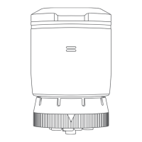
Provides dimensional outlines and mounting information for the GAD 42 with edge connectors.
Shows dimensional outlines and mounting details for the GAD 42 unit equipped with jackscrew connectors.
Illustrates the assembly process for the GAD 42 with edge connectors, showing component part numbers.
A high-level diagram illustrating the GAD 42's connections to various aircraft systems and components.
Details the specific wiring connections for power, GPS serial data, and other miscellaneous functions.
Illustrates the interconnect wiring for heading signals between the GAD 42 and compass/gyro systems.
Shows the interconnect wiring for flight control signals, connecting the GAD 42 to autopilot systems.