Installation Procedures
GDL 90 Installation Manual 560-1049-02 Rev. B 2-25
2.10 Electrical Load Analysis
The GDL 90 is powered via a separate circuit breaker. For aircraft with multiple power busses, this
circuit breaker is sourced from the non-essential bus.
An electrical load analysis should be completed on each aircraft prior to installation in accordance with
AC 43.13-1B, Chapter 11. Use the following values for computation:
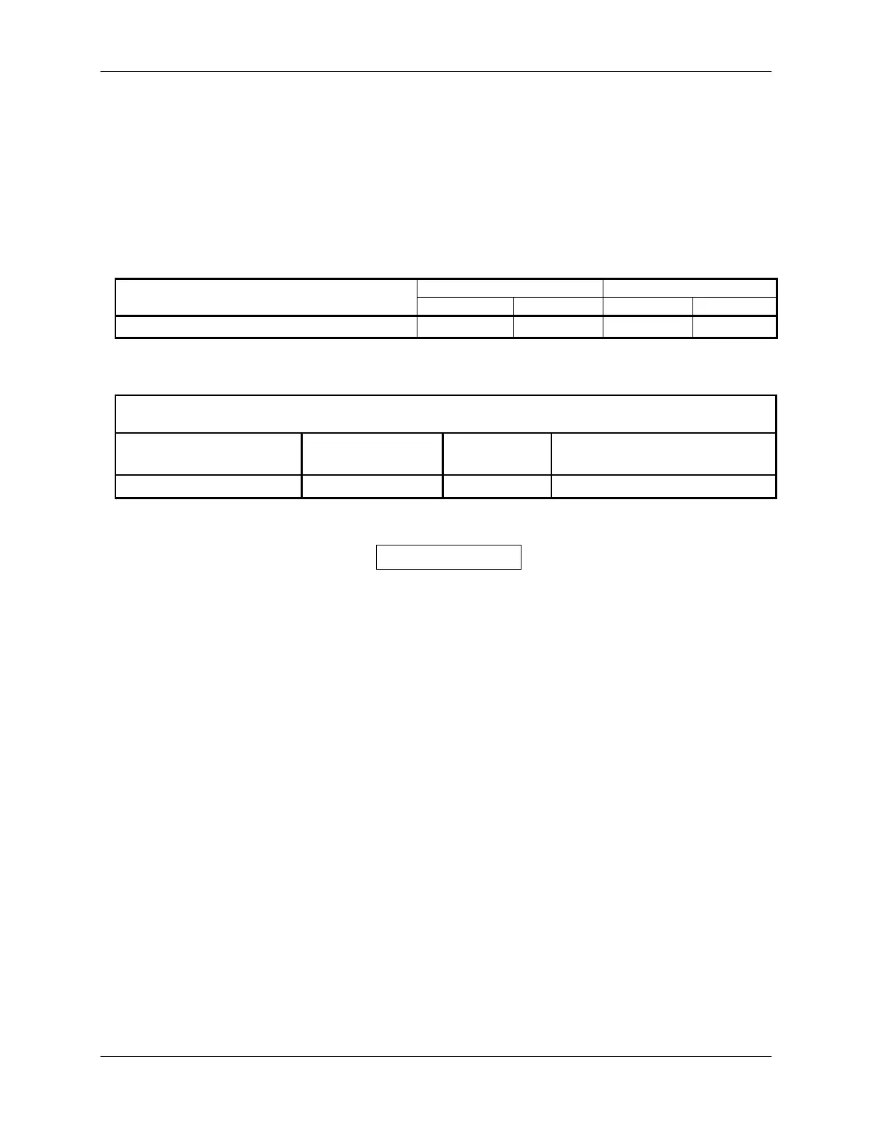
Table 2-7. Unit Power Loads
14 VDC 28 VDC
GDL 90 Input
Typical Max Typical Max
GDL 90 Main Power
1.5 A 3.00 A 750mA 1.5 A
The following table summarizes the circuit breaker and placard recommendations.
Table 2-8: Circuit Breaker Size & Placard
Unit Placard
14 VDC
Breaker Size
28 VDC
Breaker Size
GDL 90 UAT 3 A 2 A
NOTE
Circuits should be protected in accordance with guidelines in AC 43.13-1B, chapter 11,
Section 4.
 Loading...